Building The Hardware
Building the hardware
It’s time to assemble the hardware for the lab, finally! Here’s what the entire contents of the kit look like:
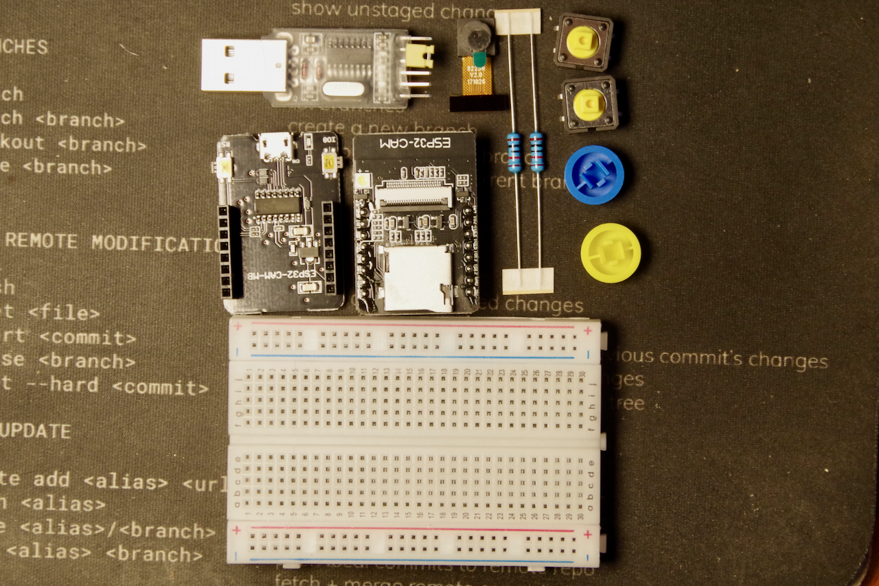
If you’re missing any pieces, please let me know. What you should have is: - 1 ESP32-Cam Board - 1 camera module - 1 programmer board - 1 breadboard - 2 10k ohm resistors - 2 tactile buttons (with colored covers) - 1 USB to TTL adapter - 11 jumper wires
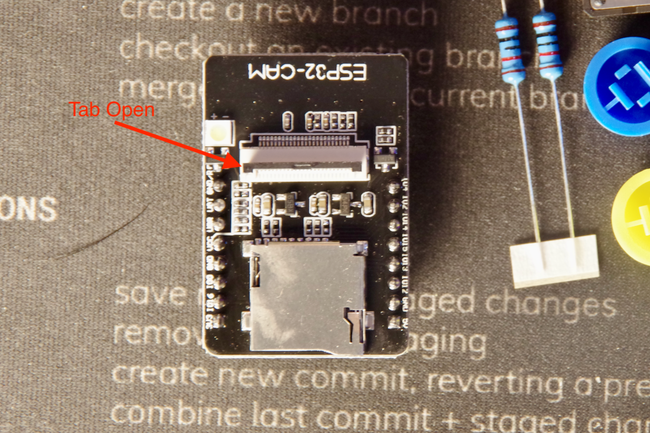
First, you’ll need to open the little black clamp on the top of the ESP32-CAM
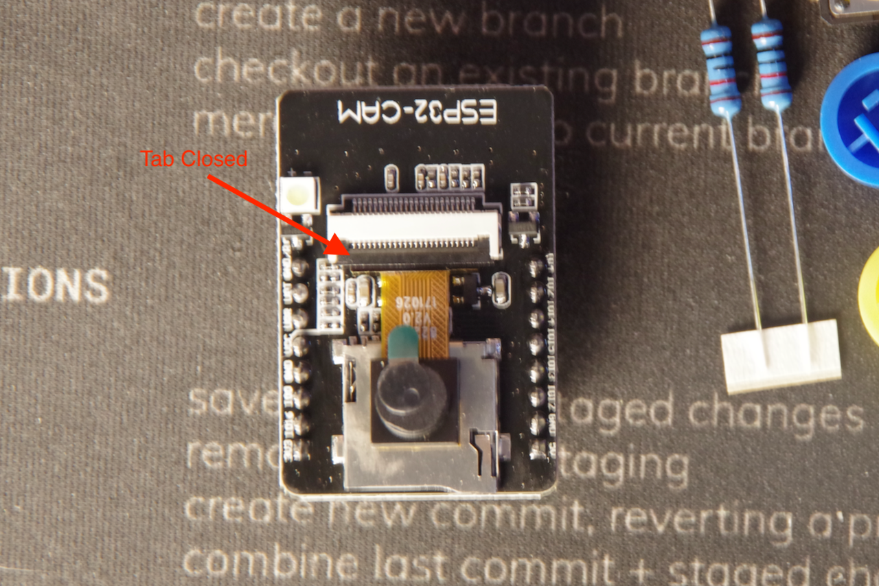
Insert the camera ribbon cable into the clamp and close the black tab completely.
Note: This is a delicate piece of plastic, so be very careful with it. Do not force it. If you do, you’ll damage the camera module.
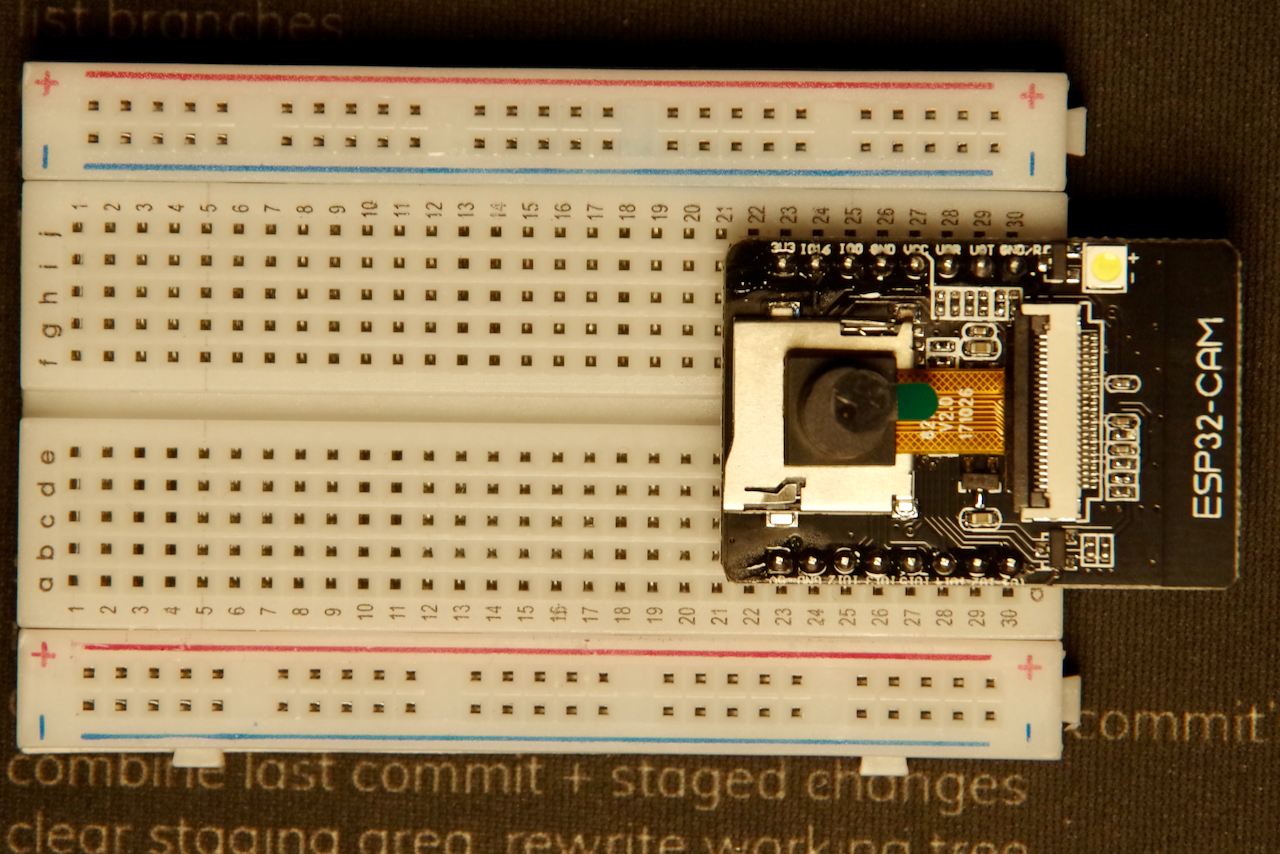
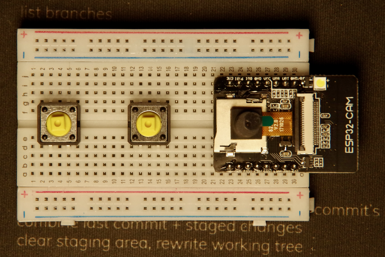
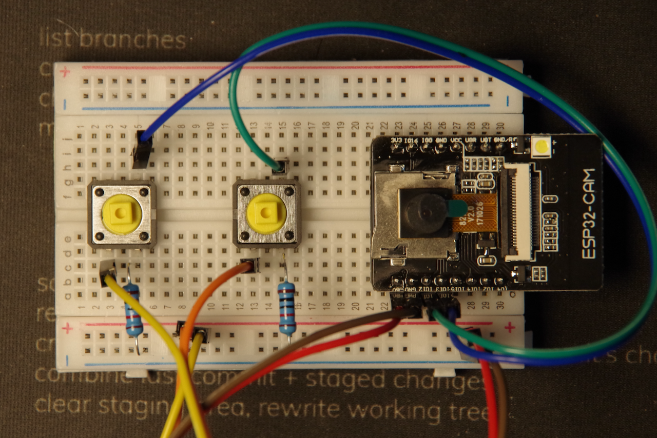
Now you can place the ESP32-CAM board on the breadboard. Put the module at one end of the breadboard, as far as it will go, with the antennae hanging off of the end of the breadboard.
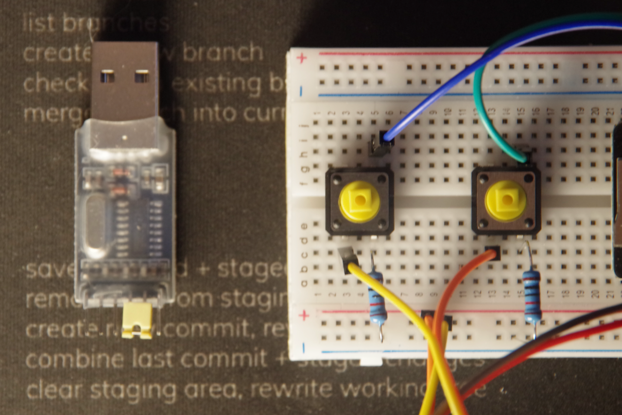
Next, place the 2 tactile buttons on the breadboard near the opposite ends. The buttons should straddle the center of the breadboard.
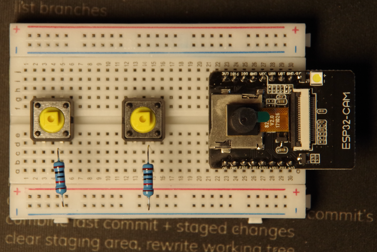
Next, bend the 2 ends of the 10k ohm resistors to 90º angles and insert them into the breadboard. One end should be in the same row as the leg of the switch nearest the camera module. The other end should go into the outside row of the breadboard marked (-).
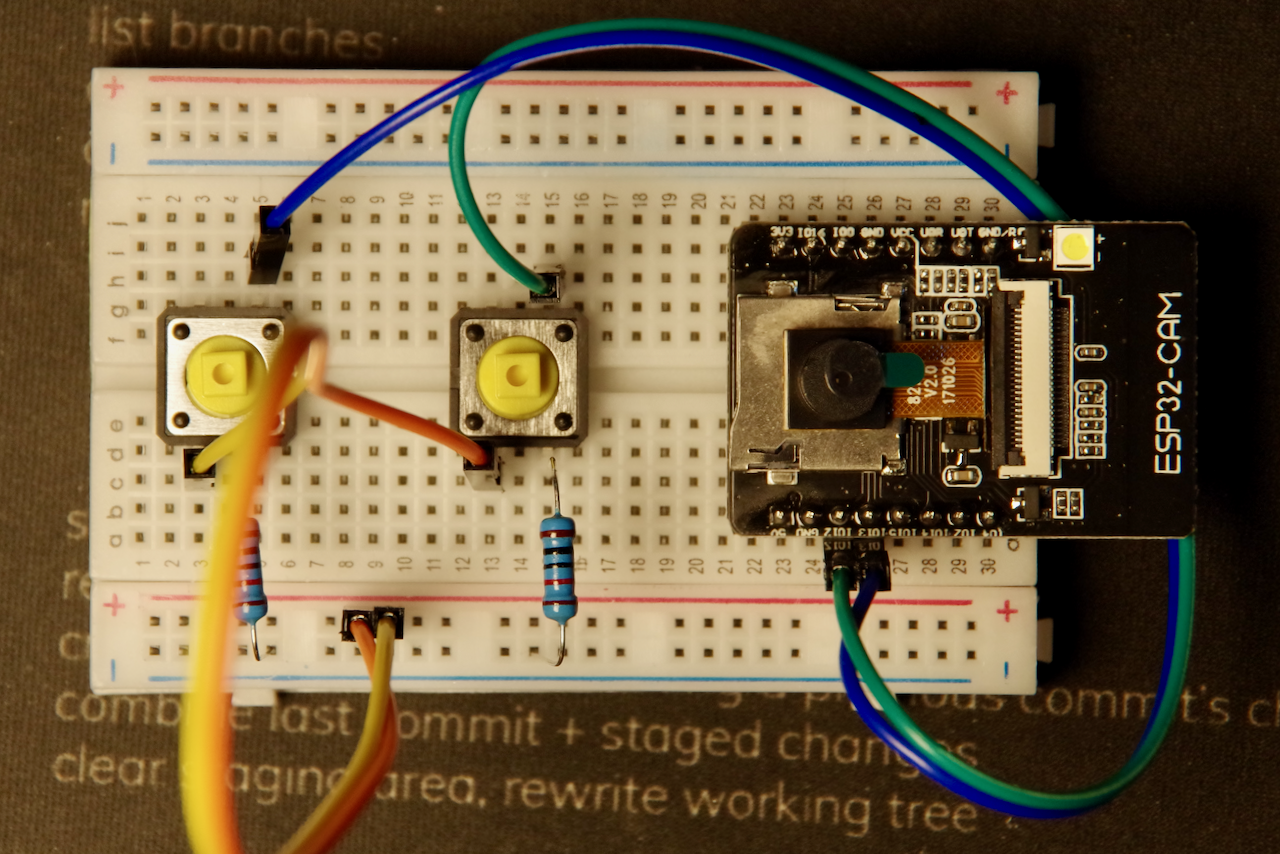
Now get one pair of jumper wires and connect them to the tactile buttons. The wires should go into the row of
the switch leg opposite from the 10k ohm resistor. The other ends of the wires should go into the rows next to
pins IO12 and IO13 on the ESP32-CAM board.
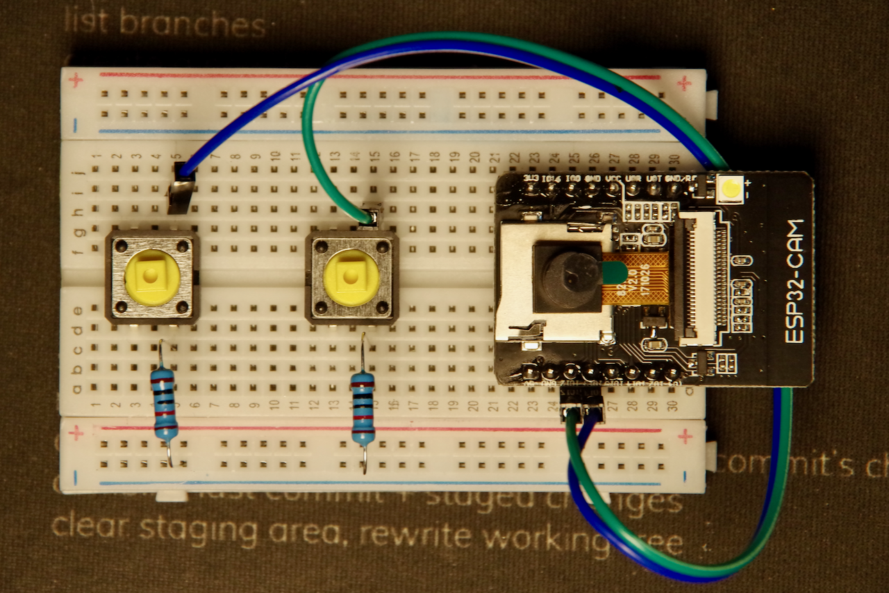
Now connect 2 more jumper wires from the other leg of the tactile switch near the 10k ohm resistors to the row marked (+) on the side of the breadboard.
Next, use 2 more jumper wires to connect the 5v and GND pins on the ESP32-CAM board
to the rows marked (+) on the side of the breadboard.
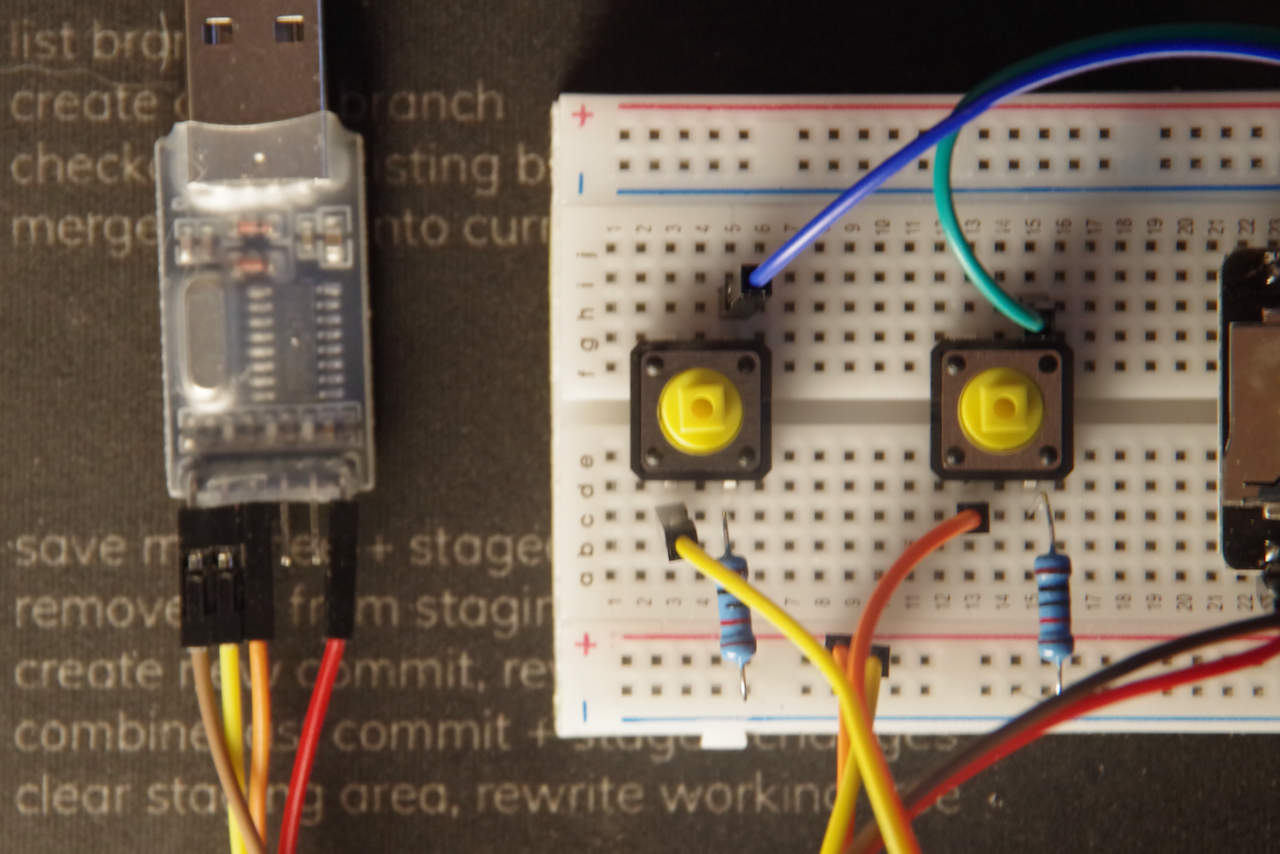
Get out the USB to TTL adapter and remove the jumper clip from it.
Connect one set of jumper wires to the 5v and GND pins on the USB to TTL adapter
and another set of jumper wires to the ``TXDandRXD` pins.
Connect the jumper wires from the 5v and GND pins on the ESP32-CAM board to the
rows marked (-) on the side of the breadboard.
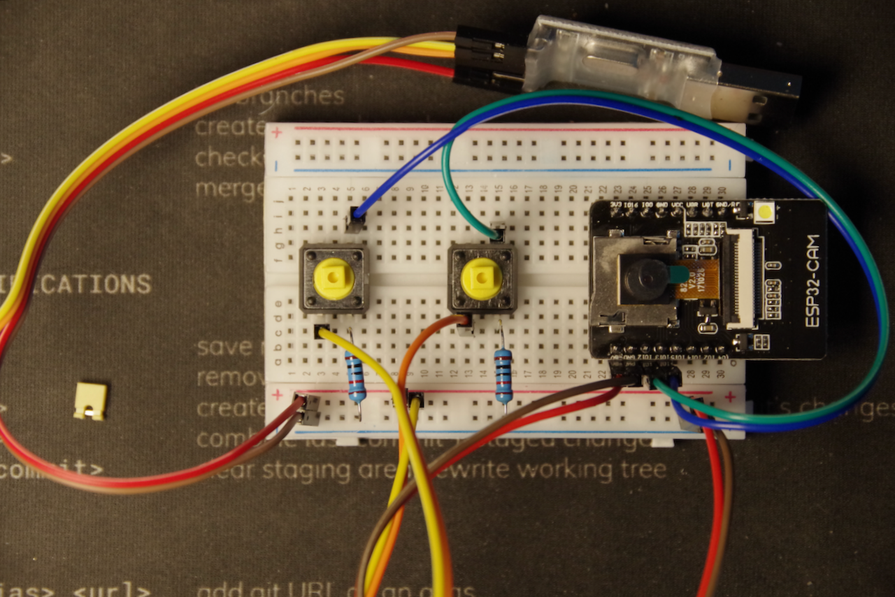
Finally connect the jumper wires from the TXD and RXD pins on the USB to TTL
adapter to the RX and TX pins on the ESP32-CAM board.
Note: Remember that the TXD pin on the USB-TTL adapter connects to the
RX pin on the ESP32-CAM board and the RXD pin on the USB-TTL adapter connects to the
TX pin on the ESP32-CAM board.
You can now add the colored button covers to your tactile buttons to complete the hardware.
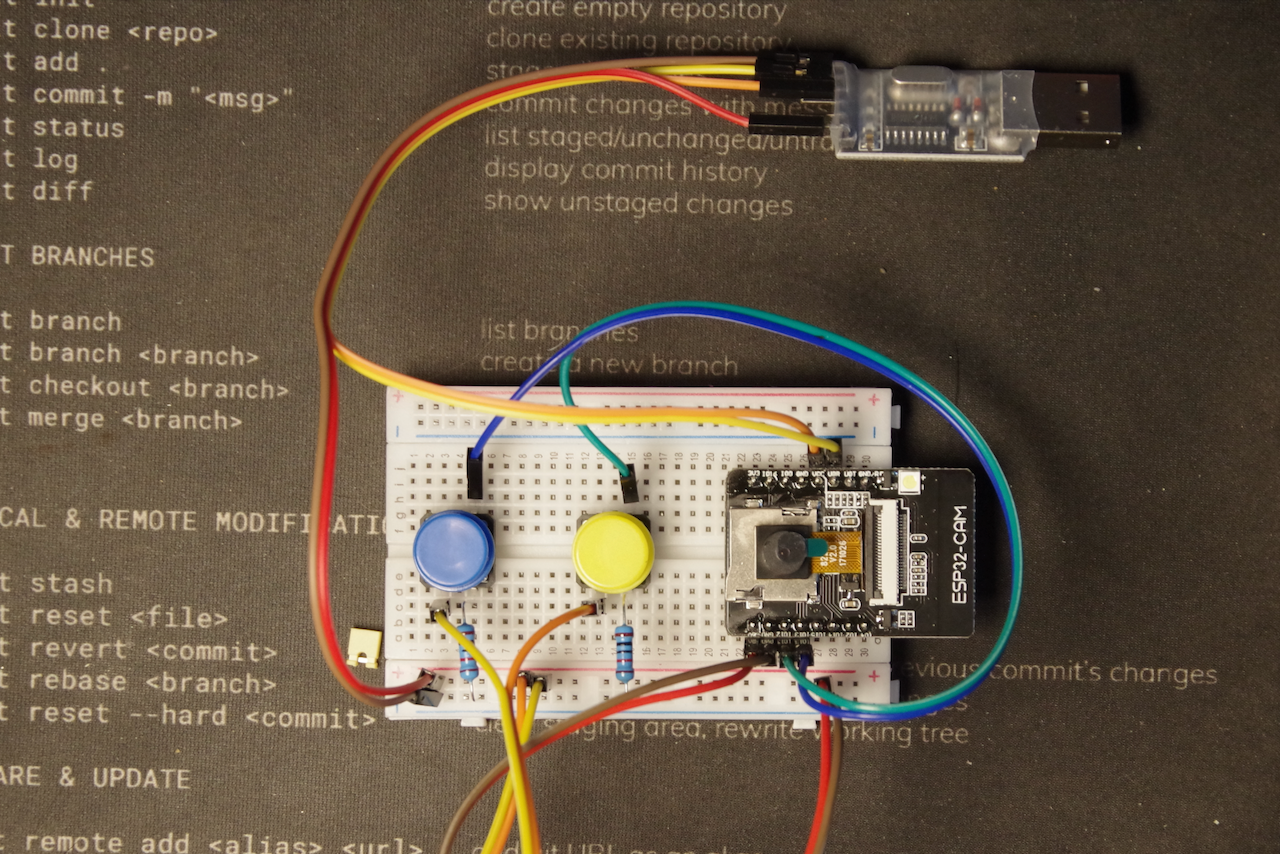
Your IoT Hardware build is now complete!