TTL Adapter
Setting up the USB to TTL (UART) adapter
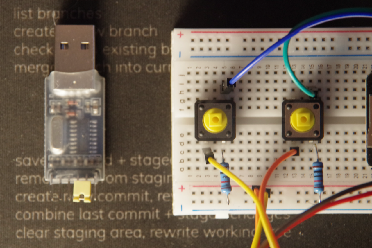
Get out the USB to TTL adapter and remove the jumper clip from it.
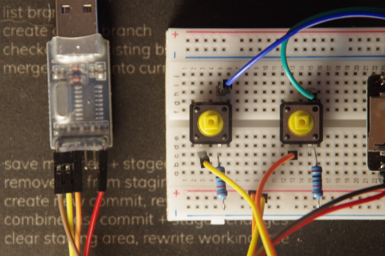
Connect one set of jumper wires to the 5v and GND pins on the USB to TTL adapter and another set of jumper wires to the ``TXDandRXD` pins.
Connect the jumper wires from the 5v and GND pins on the ESP32-CAM board to the rows marked (-) on the side of the breadboard.
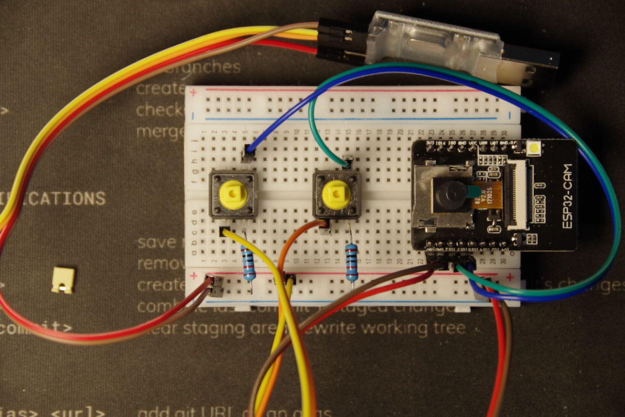
Finally connect the jumper wires from the TXD and RXD pins on the USB to TTL adapter to the RX and TX pins on the ESP32-CAM board.
Note: Remember that the TXD pin on the USB-TTL adapter connects to the RX pin on the ESP32-CAM board and the RXD pin on the USB-TTL adapter connects to the TX pin on the ESP32-CAM board.
You can now add the colored button covers to your tactile buttons to complete the hardware.
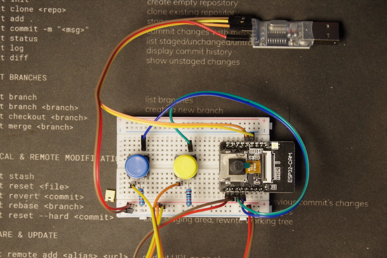
Your IoT Hardware build is now complete! Congratulations, you’re now a hardware developer!