Breadboard
Setting up the breadboard
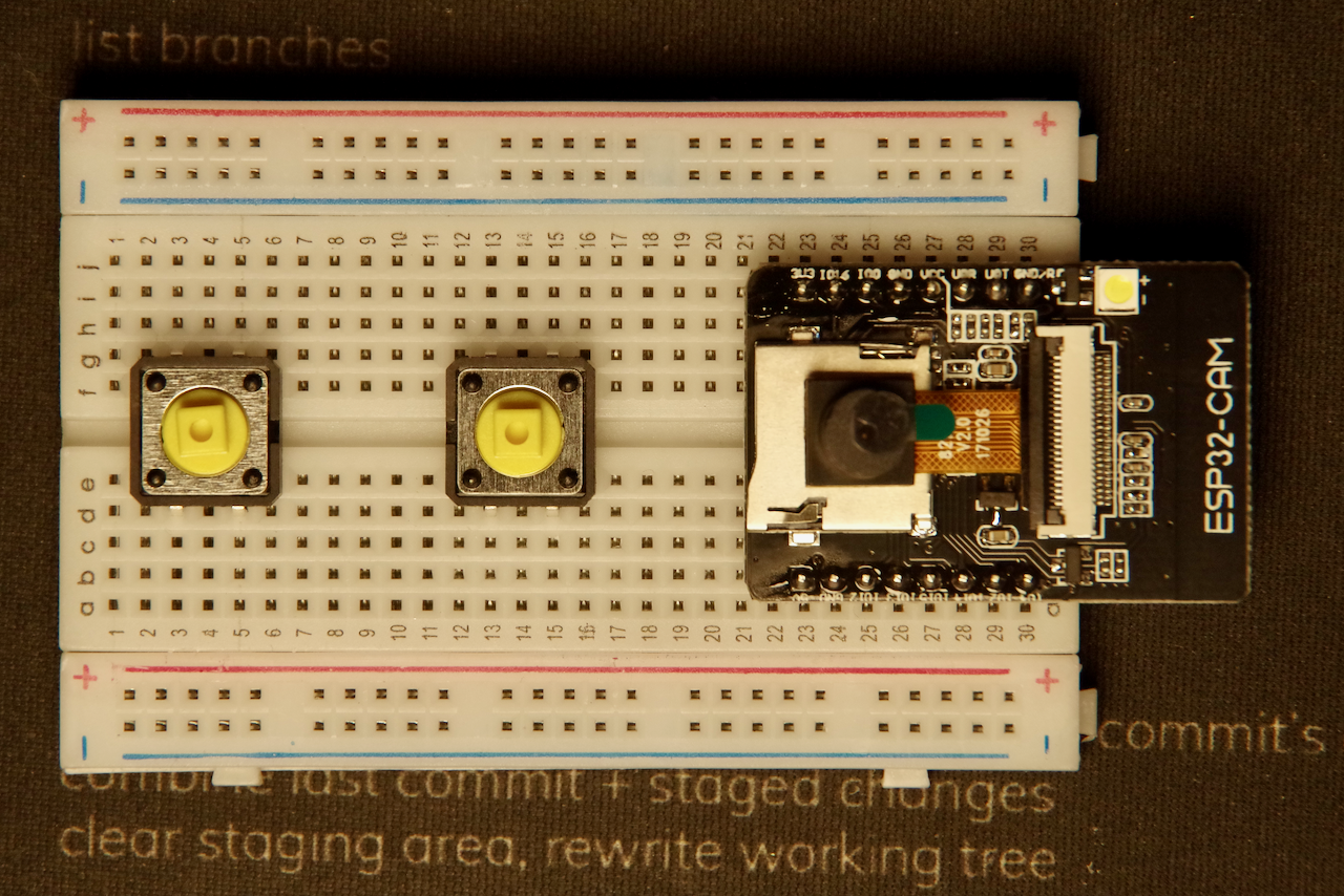
First the camera module
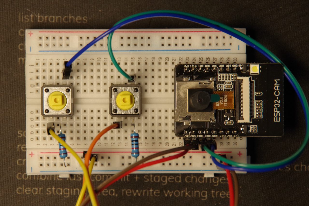
Place the ESP32-CAM board on the breadboard. Put the module at one end of the breadboard, as far as it will go, with the antennae hanging off of the end of the breadboard.
Note: You will need to use a bit of force to ensure that the camera module is seated on the breadboard. Don’t press too hard though so that you don’t damage the board.

Don’t forget to take the little lens protection sticker off of the camera module! Just pull on that little green tab and it should come right off.
Add the buttons
Next, place the 2 tactile buttons on the breadboard near the opposite ends. The buttons should straddle the center of the breadboard.
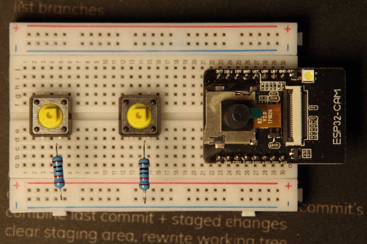
Next, bend the 2 ends of the 10k ohm resistors to 90º angles and insert them into the breadboard. One end should be in the same row as the leg of the switch nearest the camera module. The other end should go into the outside row of the breadboard marked (-).
Now get one pair of jumper wires and connect them to the tactile buttons. The wires should go into the row of the switch leg opposite from the 10k ohm resistor. The other ends of the wires should go into the rows next to pins IO12 and IO13 on the ESP32-CAM board.
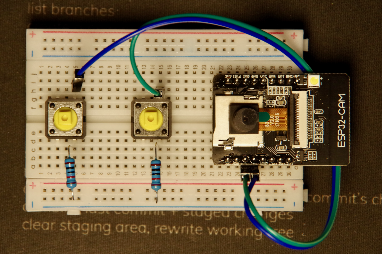
Now connect 2 more jumper wires from the other leg of the tactile switch near the 10k ohm resistors to the row marked (+) on the side of the breadboard.
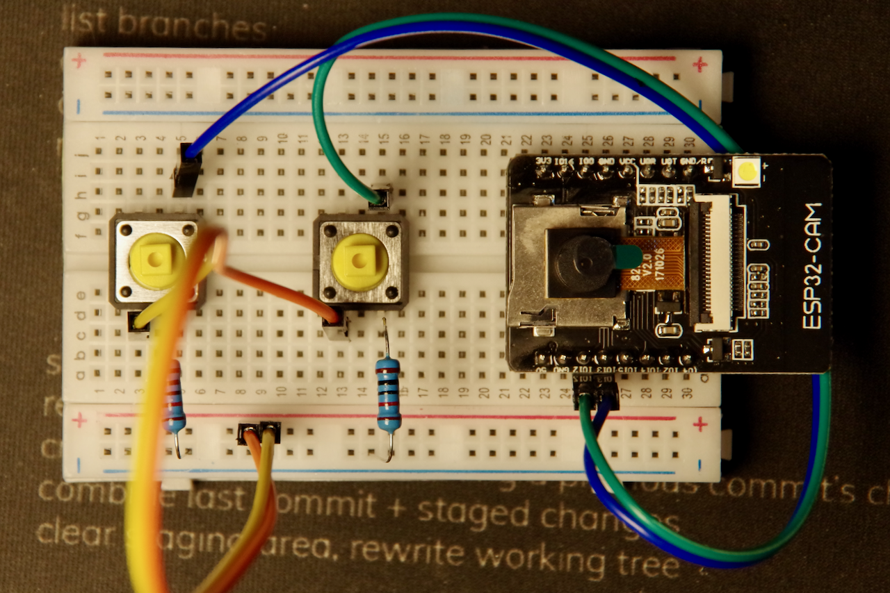
Next, use 2 more jumper wires to connect the 5v and GND pins on the ESP32-CAM board to the rows marked (+) on the side of the breadboard.
All done!
Next we’ll set ub the USB adapter so that we can talk to the board from our laptop.