


David G. Simmons
June 8, 2021
Camunda IoT Project, Part II
This is Part II in the series covering a Proof of Concept (PoC) project I’m working on as part of my job as Principal Developer Advocate at Camunda. I’m not sure how many posts will be in the series, but, well, at least two? If you missed Part I, you might want to catch up on it before continuing.
This part of the project was the first hardware build of the project. I have now built and deployed a complete outdoor weather station to gather data about current weather conditions outside the greenhouse. This will allow me to compare conditions inside the greenhouse with conditions outside the greenhouse, and compensate accordingly.
Parts List
Here is the complete parts list that I used. This differs slightly from the parts list in Part I. This is due mostly to my not being aware of a slightly different part that will make things a lot easier. It also already incorporates the lightning sensor, the BME280 for temperature, pressure and humidity, and the soil moisture input.
| Sensor | Price |
|---|---|
| Weather Station | $79.95 |
| MicroMod ESP32 | $14.95 |
| MicroMod Weather Carrier Board | $44.95 |
| LiPo Battery | $26.95 |
| Solar Charger | $26.95 |
| Solar Panel | $59.00 |
| Soil Moisture | $6.95 |
| CO2 Sensor | $59.95 |
| Total | $319.65 |
I also had an Adafruit PM2.5 sensor hanging around (it’s $44.95) so I added that too.
Building the Weather Station
Now that I had all the parts, it was time to start assembling them, and designing and printing some enclosures to hold everything. I could have made a single box to hold it all, but that would mean designing a very large box, with the requisite long print-time.
Let’s start with the power supply. Since this is going to be an outside deployment, I decided to make it solar-powered, with a battery, of course.
Powering the whole thing
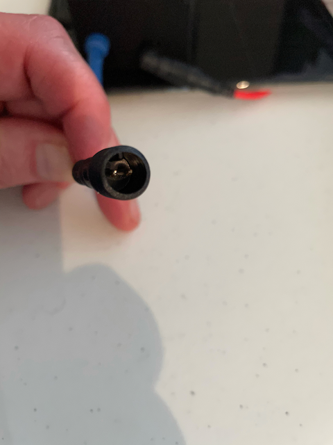
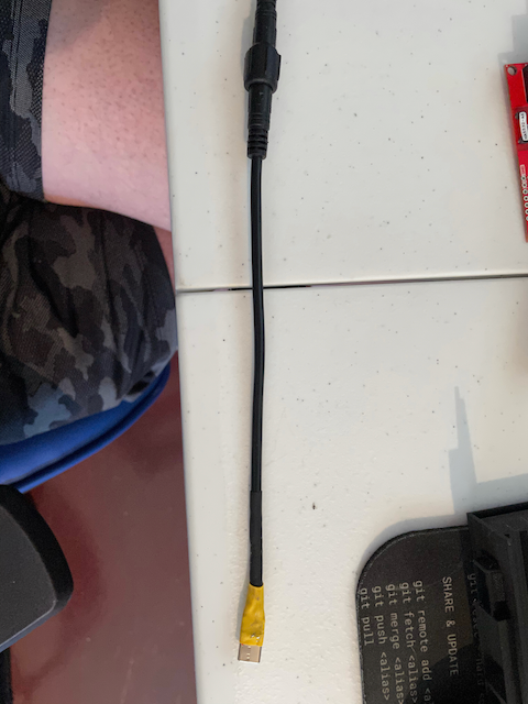
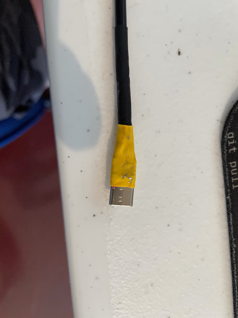
The first problem was that the Solar Buddy board does not have a USB-out. It only has a load with + and - on it. The weather station, of course, has no vcc and G pins, but only works with USB-C. So I had to fix that. Luckily I bought a boat-load of weather-proof connector wires, so I ordered some USB-C ends, and soldered one up!
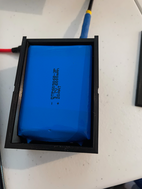
Once that was built, it was time to design a box to hold it all. Since this was going to be an outdoor device, I tried to make it waterproof by making very tight, beveled edges on the lid. The board looks small in the box:
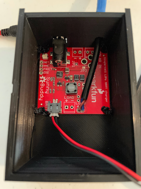
I had to solder the newly-fashioned USB-C connector on after I put the board in. And it looks small in the box, but once the battery is in, it’s a pretty full box!
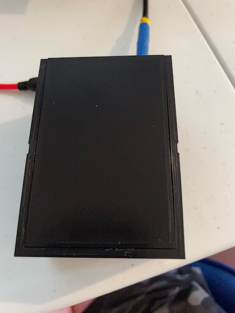
You can see the beveled edges on the lid as it is slid in:
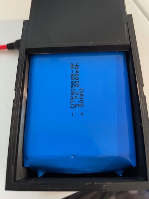
The lid is a nice tight fit, which hopefully will keep it dry!
And I even made it water-tight where the cables come out:
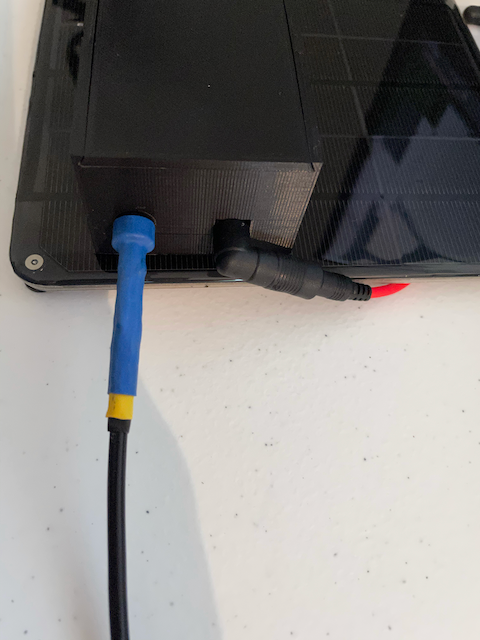
Hopefully the solar panel will keep the battery topped-off so the weather station will run continuously. I’ll need to make adjustments to the time spent sleeping in order to maximize data and minimize battery draining.
Building the Sensors
One of the advantages of using this Weather Carrier board over my previous approach is that many of the sensors I wanted to incorporate are included on the carrier board, so I had very little to actually build.
Adding the Adafruit PM2.5 was a matter of plugging in a QWIIC cable between the carrier board and the sensor. Yes, it really was that easy.
Since the QWIIC system allows pass-through, and the PM2.5 board has such a pass-through, I decided to make myself a cable for the CO2 Sensor. It involved cutting a QWIIC connector wire in half, and soldering the wires into the correct holes (I2C only requires 4 wires) on the sensor. I could then plug the CO2 sensor into the PM2.5 sensor, with minimal soldering.
For those that are curious, the SparkFun QWIIC Connect System uses 4-pin JST connectors to connect
VCC,GND,SDAandSDCon devices with the proper connector. It’s very useful and makes sensor hookups a breeze.
I now had a complete sensor system that would collect all of the outdoor environmental data I wanted on one board, with only 2 externally attached sensors. And all of that with only having to solder 4 wires.
The Sensor Enclosure
This box was going to be a bit trickier. It had to be water-tight, like the battery box, but it had to allow for constant free airflow through the device in order to get accurate readings. This sensor was nit just being deployed outside, but basically it has to be outside and unsheltered so that it can get the best readings.
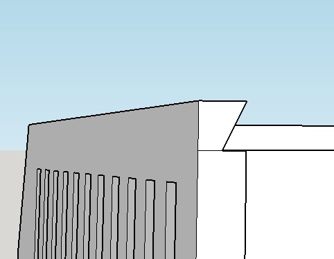
Luckily I had previously come up with a design for just such deployments. It’s a box with upward-facing louvers so that air can flow through, but rain and water cannot get in because it generally doesn’t rain up.
Here’s how they look in the 3D model rendering:
If you look closely at the open top on that model you can see that I designed the top as a slide-in with back-beveled grooves in the hopes of keeping the thing free of leaks. Where the top of the lid meets the top of the box I also back-beveled it for the same reason.
I put pins in so the board can be secured to the box (just melt the pins with the soldering iron) so there won’t be any rattling around, and the box is complete.
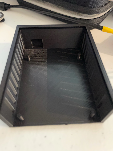
Everything then fits neatly inside the box without too much crowding (again, we need airflow!), but in minimal space.
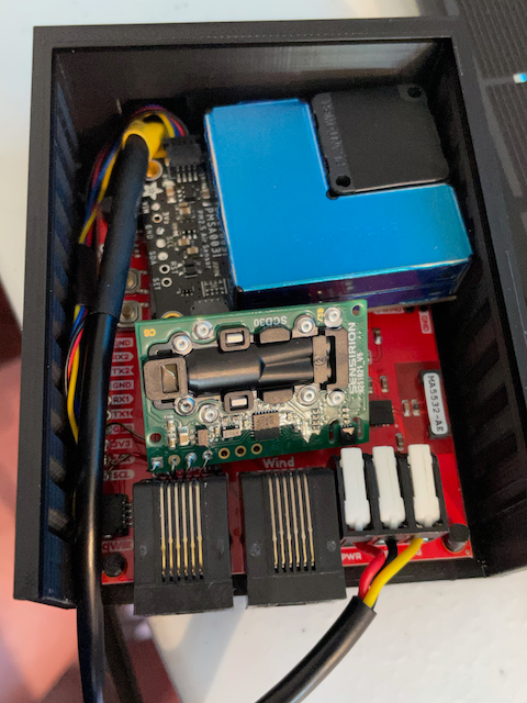
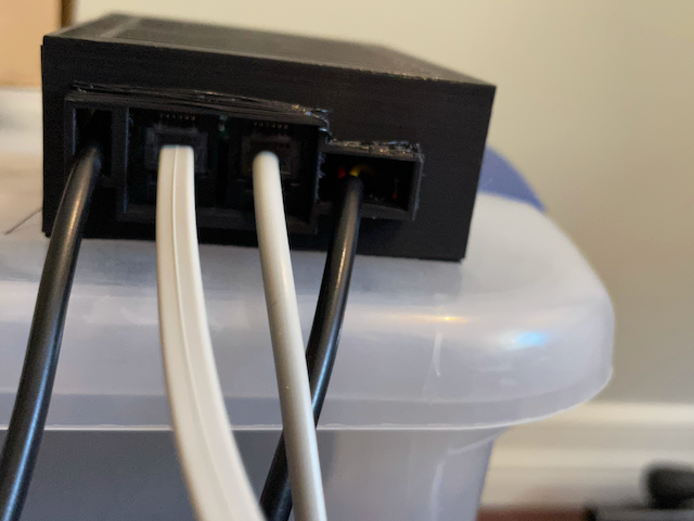
I could then slide the lid on, and plug in the weather station connectors and it’s all ready to go outside!
So that’s the hardware portion, but what about the software to make it all work? Well, read on for that!
Weather Station Software
Having all that hardware in a nice compact (and hopefully waterproof) box is great and all, but without a fair amount of software, it would all be a waste of time. So let’s dive in to some code!
Accessing the sensors
As luck would have it, SparkFun provides a nice little test program for the Weather Carrier Board which was a fantastic jumping off place for making everything work.
\*
 * This code is Lemonadeware; if you see me (or any other SparkFun employee) at the
 * local, and you've found our code helpful, please buy us a round!
 *
 * Hardware Connections:
 * Insert MicroMod processor board of your choice into the M.2 connector of the SparkFun Weather carrier
 *  Screw into place
 * Connect Weather carrier board to power useing USB-C cable
 * Connect SparkFun Soil Moisture Sensor to Weather carrier using latching terminals
 * Connect both wind and rain meters to Weather carrier using the RJ11 connectors
 */
I love the idea of “Lemonadeware”, by the way.
This example program will give me access to all the sensors except the two I added. I’ll need to add some code to join a WiFi network, so I can store the data, and I’ll need to add some code to store the data in a database, but that should be all I need to do!
First, I’ll need to import a bunch of libraries:
#include <Wire.h>
#include <SPI.h>
#include "SparkFunBME280.h"
#include <SparkFun_VEML6075_Arduino_Library.h>
#include "SparkFun_AS3935.h"
#include "SparkFun_SCD30_Arduino_Library.h"
#include <Adafruit_PM25AQI.h>
#include <InfluxDbClient.h>
#include <DNSServer.h>
#include <ESPmDNS.h>
#include <WiFiUdp.h>
#include <WiFiClientSecure.h>
#include <WiFiMulti.h>
That gives me access to all the sensors, the wifi, and InfluxDB where I’ll be storing the data for now.
I will need to define a few things as well:
#define INDOOR 0x12
#define OUTDOOR 0xE
#define LIGHTNING_INT 0x08
#define DISTURBER_INT 0x04
#define NOISE_INT 0x01
#define INFLUXDB_URL "https://my.influx.server" // define your own!
// InfluxDB v2 server or cloud API authentication token (Use: InfluxDB UI -> Data -> Tokens -> <select token>)
#define INFLUXDB_TOKEN "YOUR_TOKEN_GOES_HERE"
// InfluxDB v2 organization id (Use: InfluxDB UI -> User -> About -> Common Ids )
#define INFLUXDB_ORG "influxdata"
#define INFLUXDB_BUCKET "telegraf"
#define TZ_INFO "EST5EDT"
#define SENSOR_ID "WEA-001"
I use the SENSOR_ID as a tag in InfluxDB, and since that tag never changes, I use a #define for it.
Some variables:
WiFiMulti wifiMulti;
SCD30 airSensor;
BME280 tempSensor;
VEML6075 uv;
SparkFun_AS3935 lightning;
Adafruit_PM25AQI aqi = Adafruit_PM25AQI();
int soilPin = A0;            //Pin number that measures analog moisture signal
int soilPower = G0;          //Pin number that will power the soil moisture sensor
int WSPEED = D0;             //Digital I/O pin for wind speed
int WDIR = A1;               //Analog pin for wind direction
int RAIN = D1;               //Digital I/O pin for rain fall
const int lightningInt = G3; // Interrupt pin for lightning detection
int spiCS = G1;              //SPI chip select pin

volatile bool rainFlag = false;
volatile bool windFlag = false;

WiFiClientSecure client;
const char *ssid = "YOUR_SSID";
const char *password = "SSID_PASSWORD";
// This variable holds the number representing the lightning or non-lightning
// event issued by the lightning detector.
int intVal = 0;
int noise = 2;     // Value between 1-7
int disturber = 2; // Value between 1-10

InfluxDBClient influx(INFLUXDB_URL, INFLUXDB_ORG, INFLUXDB_BUCKET, INFLUXDB_TOKEN);
Point myPoint("weather_out");
Point aqiPoint("weather_aqi");
Since my InfluxDBv2 instance is running via TLS, I will also need to include a certificate from the cert-chain:
const char AlphaSSLCA[] PROGMEM =  R"EOF(
-----BEGIN CERTIFICATE-----
MIIETTCCAzWgAwIBAgILBAAAAAABRE7wNjEwDQYJKoZIhvcNAQELBQAwVzELMAkG
A1UEBhMCQkUxGTAXBgNVBAoTEEdsb2JhbFNpZ24gbnYtc2ExEDAOBgNVBAsTB1Jv
b3QgQ0ExGzAZBgNVBAMTEkdsb2JhbFNpZ24gUm9vdCBDQTAeFw0xNDAyMjAxMDAw
MDBaFw0yNDAyMjAxMDAwMDBaMEwxCzAJBgNVBAYTAkJFMRkwFwYDVQQKExBHbG9i
YWxTaWduIG52LXNhMSIwIAYDVQQDExlBbHBoYVNTTCBDQSAtIFNIQTI1NiAtIEcy
MIIBIjANBgkqhkiG9w0BAQEFAAOCAQ8AMIIBCgKCAQEA2gHs5OxzYPt+j2q3xhfj
kmQy1KwA2aIPue3ua4qGypJn2XTXXUcCPI9A1p5tFM3D2ik5pw8FCmiiZhoexLKL
dljlq10dj0CzOYvvHoN9ItDjqQAu7FPPYhmFRChMwCfLew7sEGQAEKQFzKByvkFs
MVtI5LHsuSPrVU3QfWJKpbSlpFmFxSWRpv6mCZ8GEG2PgQxkQF5zAJrgLmWYVBAA
cJjI4e00X9icxw3A1iNZRfz+VXqG7pRgIvGu0eZVRvaZxRsIdF+ssGSEj4k4HKGn
kCFPAm694GFn1PhChw8K98kEbSqpL+9Cpd/do1PbmB6B+Zpye1reTz5/olig4het
ZwIDAQABo4IBIzCCAR8wDgYDVR0PAQH/BAQDAgEGMBIGA1UdEwEB/wQIMAYBAf8C
AQAwHQYDVR0OBBYEFPXN1TwIUPlqTzq3l9pWg+Zp0mj3MEUGA1UdIAQ+MDwwOgYE
VR0gADAyMDAGCCsGAQUFBwIBFiRodHRwczovL3d3dy5hbHBoYXNzbC5jb20vcmVw
b3NpdG9yeS8wMwYDVR0fBCwwKjAooCagJIYiaHR0cDovL2NybC5nbG9iYWxzaWdu
Lm5ldC9yb290LmNybDA9BggrBgEFBQcBAQQxMC8wLQYIKwYBBQUHMAGGIWh0dHA6
Ly9vY3NwLmdsb2JhbHNpZ24uY29tL3Jvb3RyMTAfBgNVHSMEGDAWgBRge2YaRQ2X
yolQL30EzTSo//z9SzANBgkqhkiG9w0BAQsFAAOCAQEAYEBoFkfnFo3bXKFWKsv0
XJuwHqJL9csCP/gLofKnQtS3TOvjZoDzJUN4LhsXVgdSGMvRqOzm+3M+pGKMgLTS
xRJzo9P6Aji+Yz2EuJnB8br3n8NA0VgYU8Fi3a8YQn80TsVD1XGwMADH45CuP1eG
l87qDBKOInDjZqdUfy4oy9RU0LMeYmcI+Sfhy+NmuCQbiWqJRGXy2UzSWByMTsCV
odTvZy84IOgu/5ZR8LrYPZJwR2UcnnNytGAMXOLRc3bgr07i5TelRS+KIz6HxzDm
MTh89N1SyvNTBCVXVmaU6Avu5gMUTu79bZRknl7OedSyps9AsUSoPocZXun4IRZZ
Uw==
-----END CERTIFICATE--reading_time: 15 minutes
---
)EOF";
Then I can get everything set up in my setup() function:
void setup() {
  Serial.begin(115200);
  while (!Serial)
    ;
  delay(2500);
  Wire.begin(); // start I2C
  SPI.begin();  // Start SPI

  if (tempSensor.beginI2C() == false) { //Begin communication over I2C
    Serial.println("BME280 did not respond.");
    while (1)
      ; // Freeze
  }
  Serial.println("BME 280 found ...");
  if (uv.begin() == false) {
    Serial.println("VEML6075 did not respond.");
    while (1)
      ; // Freeze
  }
  Serial.println("VEML 6075 found ...");
  if (airSensor.begin() == false) {
    Serial.println("Air sensor not detected. Please check wiring. Freezing...");
    while (1)
      ; // Freeze
  }
  if (!aqi.begin_I2C()) { // connect to the sensor over I2C
    Serial.println("Could not find PM 2.5 sensor!");
    while (1)
      ; // Freeze
  }
  Serial.println("PM 2.5 found!");
  pinMode(LED_BUILTIN, OUTPUT);
  pinMode(soilPower, OUTPUT);
  digitalWrite(soilPower, LOW);
  // When lightning is detected the interrupt pin goes HIGH.
  pinMode(lightningInt, INPUT);
  //Initialization for weather meter
  pinMode(WSPEED, INPUT_PULLUP); //Input from wind meters windspeed sensor
  pinMode(RAIN, INPUT_PULLUP);   //Input from wind meters rain gauge sensor
  //attach external interrupt pins to IRQ functions
  attachInterrupt(digitalPinToInterrupt(RAIN), rainIRQ, FALLING);
  attachInterrupt(digitalPinToInterrupt(WSPEED), wspeedIRQ, FALLING);
  //turn on interrupts
  interrupts();

//TODO: this should go away once variant file is written
#if defined(ESP_PLATFORM)
  SPI.begin(14, 2, 15);
#endif

  if (lightning.beginSPI(spiCS, 2000000) == false) {
    Serial.println("Lightning Detector did not start up, freezing!");
    while (1)
      ; // Freeze
  }
  Serial.println("Schmow-ZoW, Lightning Detector Ready!");
  // The lightning detector defaults to an indoor setting at
  // the cost of less sensitivity, if you plan on using this outdoors
  // uncomment the following line:
  lightning.setIndoorOutdoor(OUTDOOR);
  // All the sensors are now properly configured.
  // Start WiFi
  WiFi.mode(WIFI_STA);
  Serial.printf("Wi-Fi mode set to WIFI_STA %s\n", WiFi.mode(WIFI_STA) ? "" : "Failed!");
  WiFi.begin(ssid, password);
  Serial.print("Waiting for WiFi to connect...");
  int i=0;
  while (WiFi.status() != WL_CONNECTED && i<30) {
    Serial.print(".");
    delay(500);
    i++;
  }
  Serial.println();
  if(WiFi.status() != WL_CONNECTED) {
    Serial.println("WiFi failed");
    ESP.restart();
  }
  WiFi.printDiag(Serial);
  Serial.println(WiFi.psk().c_str());
  influx.setWriteOptions(WriteOptions().writePrecision(WritePrecision::MS));
  influx.setWriteOptions(WriteOptions().batchSize(10).bufferSize(50));
  WiFiClientSecure *client = new WiFiClientSecure;
  if(client) {
    // set the cert for TLS
    client -> setCACert(AlphaSSLCA);
  // Check server connection
    if (influx.validateConnection()) {
      Serial.print("Connected to InfluxDB: ");
      Serial.println(influx.getServerUrl());
    } else {
      Serial.print("InfluxDB connection failed: ");
      Serial.println(influx.getLastErrorMessage());
      waitForInflux();
    }
  }
  // Set up global tags, etc. for the 2 Points weather and Air Quality Index
  myPoint.addTag("sensor", "weather_01");
  myPoint.addTag("location", "Apex");
  myPoint.addTag("Sensor_id", SENSOR_ID);
  aqiPoint.addTag("sensor", "weather_01");
  aqiPoint.addTag("location", "Apex");
  aqiPoint.addTag("Sensor_id", SENSOR_ID);
  Serial.println("Ready!");
}
At this point, the entire system is now set up, connected to all the sensors, connected to WiFi, and connected to InfluxDB. From here on out it’s a matter of handling the interrupts, reading the sensors, and writing the data.
In order to handle the interrupts, we have to have functions to deal with them:
//Function is called every time the rain bucket tips
void rainIRQ() {
  rainFlag = true;
}

//Function is called when the magnet in the anemometer is activated
void wspeedIRQ() {
  windFlag = true;
}
Now we can write our main loop() to collect and send data.
void loop() {
  myPoint.clearFields(); // clear out the previous data
  if (influx.isBufferFull()) {
    influx.setInsecure(false);
    influx.flushBuffer();
  }
  digitalWrite(LED_BUILTIN, HIGH); // turn the LED on (HIGH is the voltage level)
  int rssi = WiFi.RSSI();
  myPoint.addField("RSSI", rssi);
  myPoint.addField("temp", tempSensor.readTempC());
  myPoint.addField("humidity", tempSensor.readFloatHumidity());
  myPoint.addField("pressure", tempSensor.readFloatPressure());
  myPoint.addField("altitude", tempSensor.readFloatAltitudeFeet());
  myPoint.addField("uva", uv.uva());
  myPoint.addField("uvb", uv.uvb());
  myPoint.addField("uv_index", uv.index());
  myPoint.addField("soil_moisture", readSoil());
  myPoint.addField("wind_degrees", getWindDirection());
  //Check interrupt flags
  if (rainFlag == true) {
    rainFlag = false;
    myPoint.addField("rain", 0.2794); // each bucket-tip is 0.2794" of rain
  }
  // if the anemometer is moving, we will take 30 readings and use that for our wind-speed
  if (windFlag == true) {
    windFlag = false;
    int speed = 0;
    for (int x = 0; x < 30; x++) {
      if (WSPEED) {
        speed++;
      }
      delay(100);
    }
    double w_speed = (speed * 3.33) * 2.4;
    myPoint.addField("wind_speed", speed);
  }
  // get data from the CO2 sensor. We can use its temp/humidity to validate the BME280
  if (airSensor.dataAvailable()) {
    int co2 = airSensor.getCO2();
    float temp_c = airSensor.getTemperature();
    float hum = airSensor.getHumidity();
    myPoint.addField("co2", co2);
    myPoint.addField("c_temp_c", temp_c);
    myPoint.addField("c_humidity", hum);
  }
  read_aqi();
  // Hardware has alerted us to an event, now we read the interrupt register
  if (digitalRead(lightningInt) == HIGH) {
    intVal = lightning.readInterruptReg();
    if (intVal == NOISE_INT) {
      // Too much noise? Uncomment the code below, a higher number means better
      // noise rejection.
      //lightning.setNoiseLevel(noise);
    }
    else if (intVal == DISTURBER_INT) {
      // Too many disturbers? Uncomment the code below, a higher number means better
      // disturber rejection.
      //lightning.watchdogThreshold(disturber);
    } else if (intVal == LIGHTNING_INT) {
      // Lightning! Now how far away is it? Distance estimation takes into
      // account any previously seen events in the last 15 seconds.
      byte distance = lightning.distanceToStorm();
      myPoint.addField("lightning_event", true);
      myPoint.addField("ligthning_km", distance);
    }
  }
  influx.writePoint(myPoint);
  digitalWrite(LED_BUILTIN, LOW); // turn the LED off by making the voltage LOW
  // may have to adjust this for battery life
  delay(3000);
}
The only thing that isn’t covered in there is the reading of the PM2.5 sensor, which I moved to the read_aqi() function, the reading of the soil moisture, which is in the readSoil() function, and getting the wind direction which is in the getWindDirection() function:
void read_aqi() {
  aqiPoint.clearFields();
  PM25_AQI_Data data;
  if (!aqi.read(&data)) {
    Serial.println("Could not read from AQI");
    return;
  }
  aqiPoint.addField("pm_10_stand", data.pm10_standard);
  aqiPoint.addField("pm_25_stand", data.pm25_standard);
  aqiPoint.addField("pm_100_stand", data.pm100_standard);
  aqiPoint.addField("pm_10_env", data.pm10_env);
  aqiPoint.addField("pm_25_env", data.pm25_env);
  aqiPoint.addField("pm_100_env", data.pm100_env);
  aqiPoint.addField("part_03um", data.particles_03um);
  aqiPoint.addField("part_05um", data.particles_05um);
  aqiPoint.addField("part_10um", data.particles_10um);
  aqiPoint.addField("part_25um", data.particles_25um);
  aqiPoint.addField("part_50um", data.particles_50um);
  aqiPoint.addField("part_100um", data.particles_100um);
  influx.writePoint(aqiPoint);
}

int readSoil() {
  int moistVal = 0; //Variable for storing moisture value
  //Power Sensor
  digitalWrite(soilPower, HIGH);
  delay(10);
  moistVal = analogRead(soilPin); //Read the SIG value from sensor
  digitalWrite(soilPower, LOW);   //Turn the sensor off
  return moistVal;                //Return current moisture value
}

int getWindDirection() {
  unsigned int adc;
  adc = analogRead(WDIR); //get the current readings from the sensor
  if (adc < 380)
    return (113);
  if (adc < 393)
    return (68);
  if (adc < 414)
    return (90);
  if (adc < 456)
    return (158);
  if (adc < 508)
    return (135);
  if (adc < 551)
    return (203);
  if (adc < 615)
    return (180);
  if (adc < 680)
    return (23);
  if (adc < 746)
    return (45);
  if (adc < 801)
    return (248);
  if (adc < 833)
    return (225);
  if (adc < 878)
    return (338);
  if (adc < 913)
    return (0);
  if (adc < 940)
    return (293);
  if (adc < 967)
    return (315);
  if (adc < 990)
    return (270);
  return (-1);
}
And that gives me everything I need. All the sensor data is collected, and written to InfluxDB.
All I have to do is take it all outside and let it rip! Then login to my InfluxDB instance and see if data is coming in:
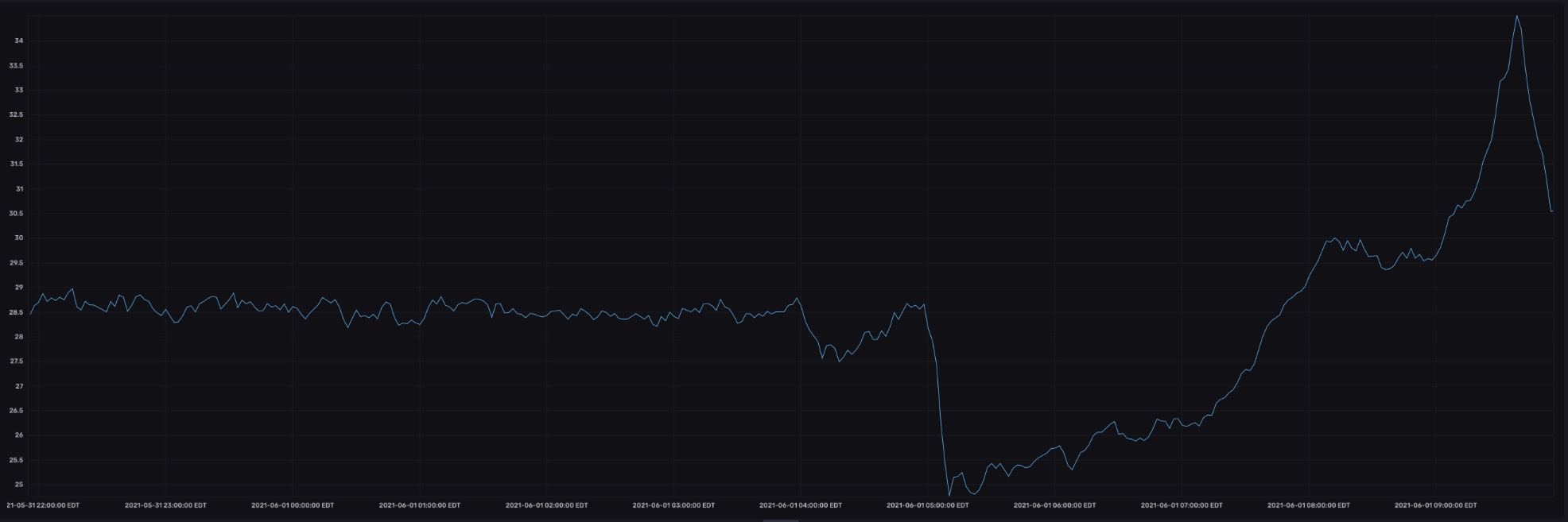
Yep, that’s the temperature data coming in alright!
Conclusion
I now have a fully functioning weather station that collects temperature, pressure and humidity data, lightning strike data, CO2 data, and air particulate data and stores it all in a database.
The next step is to build and deploy all the sensors for the greenhouse (the interior sensors). Once I have all of those deployed, I can start triggering events from the database.
After the database is properly triggering events, it will be time (finally!) to define some BPMN processes around those events so that I can properly control the environment inside my greenhouse based on conditions both inside and outside the greenhouse. I’m really excited about that last part.
I’d love to hear from you about how you think I can use Camunda to control the greenhouse conditions. I have my own ideas, but I’d love to hear yours!
 English
 Deutsche
 Dutch
Dutch Español
 Français