


David G. Simmons
July 20, 2018
Building an InfluxDB IoT Edge Data Collection Device
I’ve been saying I was going to write this whole project up for some time now but it has been such a daunting task that I’ve been putting it off, starting and stopping, and generally not getting it done for a few months. Finally, I have it! This is both a hardware build and a software build, and there are a lot of moving parts, so be prepared!
Overview
I wanted to build a demonstration system that would show off the capabilities of using InfluxData — the entire TICK Stack — on the extreme edge of an IoT Architecture. While a lot of companies are betting on the cloud for IoT data collection, I understand that for some — especially in the Industrial IoT space — a cloud-first strategy is simply a non-starter. Furthermore, with a wide variety of network connectivity modalities — WiFi, BLE, LoRAWAN, etc. — being deployed, at some point you simply have to have an edge device to connect to your end-sensors. In essence, I wanted to pull this architecture diagram together in real life.
So I had to build a bunch of sensors, and then build an edge data collection box, and then hook it up to the internet and have it back-haul data to the cloud. Let’s start with the sensor builds.
The Hardware
As stated above, I wanted to incorporate as many sensors , and communication protocols, as I could in order to cover the widest possible deployment scenario. I ended up building a CO2 sensor connected over BlueTooth Low Energy (BLE), a temperature, humidity, pressure, visible light and Infrared sensor connected over WiFi, a radiation sensor connected over LoRAWAN and a contactless temperature sensor also connected over LoRaWan. That’s a lot of sensors to build, and a lot of RF protocols to incorporate.
The WiFi Sensor
Let’s tackle this one first, shall we? Here is the parts list you need to build this one:
- Particle Photon
- Bosch BME280 (I got mine from Adafruit)
- Adafruit TLS2561 Light sensor
I used I2C to hook them up, since it used the fewest pins, and I could share the pins. Here’s the wiring Diagram:
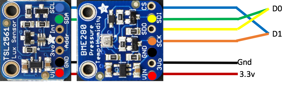
I wired them to my Particle Photon and wrote a little bit of software. We’ll get to that in the Software Section, but it was fairly trivial to do given that Particle devices are programmed in an Arduino-like language and are fairly straightforward to handle.
I 3-D printed a nice box for it, and used super-thin ceramic-coated wire to solder it all together so it came out in a nice package:
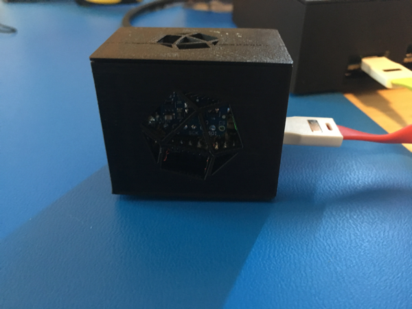
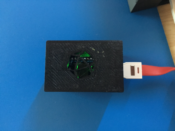
The sensor boards are hung from the insides, in front of the ventilation holes, so that they can get accurate (sort of) readings.
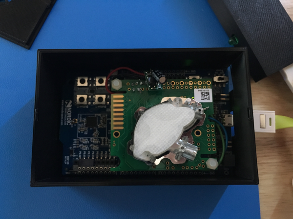
The BLE CO2 Sensor
This one was a bit more of a challenge for a few reasons. But first the parts list:
- Nordic nRF52DK developer Kit (I got mine from DigiKey)
- SenseAir K30 CO2 sensor
- 4700µF Capacitor(Adafruit to the rescue again!)
- 9v Boost Converter (I got mine from Pololu)
To make things a little less complicated, I wired the Boost to the nRF52, and then put the capacitor on the vout of the boost like this:
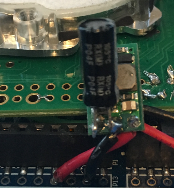
I’m not certain it made things easier per se, but it was how I did it anyway. If you’re an electrical engineer, and are laughing right now, feel free to get in touch and point out the error of my ways.
I’ll get in to it more in the software sections, but this one was a bit of a beast to control. First off, DO NOT use this sensor wired directly to an Arduino! It absolutely will eat your voltage regulator. It requires 5v-12v and 500mA and according to the manufacturer, there isn’t an Arduino out there with a regulator that can handle it. The nRF52DK board claims that they can, but I’m skeptical of that claim to some degree.
Again, I 3-D printed a nice box, with vent holes in the top to allow for airflow.
I keep looking for a smaller BLE-based board to drive this thing — one that does not run Arduino — but I’ve yet to find the right one.
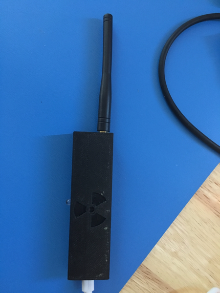
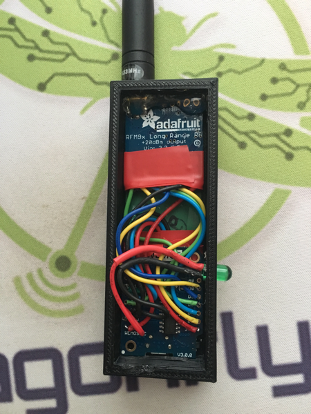
The LoRa Radiation Sensor
This one was super fun to build. I grew up in Los Alamos, NM (The Atomic City!), so there’s that. But I had been invited to present at a workshop in Italy hosted by the United Nations International Atomic Energy Agency on “Radiation Monitoring over LoRaWAN” so I just had to build a radiation sensor! (It was really neat, and I blogged about it here)
Here’s what I used:
- Pocket Geiger Radiation Sensor (from SparkFun Electronics)
- Wemos D1 Mini (I do not recommend the D1 Mini Pro as all the ones I bought had faulty WiFi and were unusable, though I did not use the WiFi for these parts)
- LoRa Radio Board (from Adafruit, of course)
- A White LED
You’re probably asking yourself why I used a Wemos D1 (which has WiFi) inside this thing that is using a LoRa radio, and I’ll tell you why: I couldn’t find a cheaper board to control the LoRa Radio Board and the sensor board. At $3.00 it was just the right thing. I just turned the WiFi off and went with it.
For the LED I just used one I had lying around. No idea where it came from.
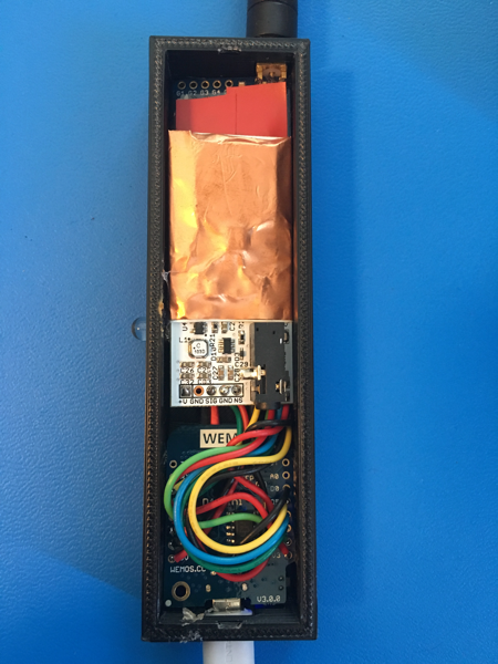
This one came out really nicely!
As you can see, it took a fair amount of work to get everything in the box, what with all the wires, etc. but it all managed to fit snugly.
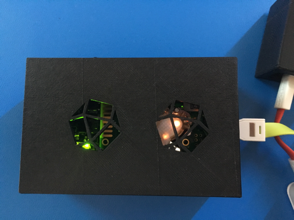
The Contactless Temperature Sensor
Again, super simple.
- Wemos D1 Mini (see above)
- LoRad Radio Board (see above)
- Melexis MLX90614 sensor (You can get one from Adafruit)
- A green LED
I’ll admit that you can’t get the same Melexis sensor that I used but that’s because way back in the day, back in the Project Sun SPOT days, we built a little sensor board for the MLX90614 that made it easy to use over I2C. I happen to have a few of those lying around (from like 2006!), so I used one. Again, I used the Wemos D1 Mini, with the WiFi radio turned off, to control both the sensor and the LoRa Board simply because it was cheap (and I had a bunch of Wemos D1 Mini Pros lying around with Wifi that didn’t work anyway. Remember, don’t buy those.)
Same thing with the Green LED. Just had one lying around.
Here’s the Temperature sensor board you can’t have:
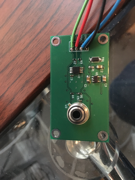
And here’s the final package:
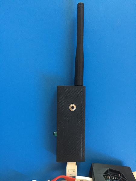
Again, getting all the wires in took some nifty soldering and packaging, but it all managed to fit in the end:
So that concludes the sensor hardware. Now, on to the Edge Data Collection Node Hardware!
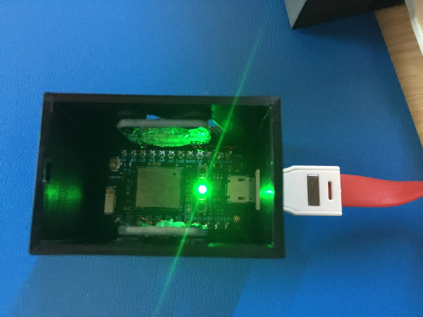
Building the Edge Collector
I admit that I could have used a Raspberry Pi. But honestly I’d backed the Pine-64 on Kickstarter and I hadn’t used the board for anything, so I decided to use it. Also, finding screens and cases for Raspberry Pis is easy, I guess, but there are so many of them that it was hard to choose, and Pine64 has it all in one place.
Here’s what I needed for the build:
- Pine-64 LTS Main Board ($32.00)
- WiFi/BLE card ($9.99)
- 7” TFT Touchscreen ($35.99)
- Pine64 Playbox Enclosure ($9.99)
- LiPo Battery ($21.99)
- LoRa Board (see above)
- Wemos D1 Mini (see above)
Optional but recommended
- 64GB EMMC Module ($34.95)
I actually used a 64GB MicroSSD card in mine, but the location of the card slot is so awful that I ended up breaking one and having to replace it. If I had to build another one, I’d use the EMMC Module for sure.
I’m sure you’re scratching your head and thinking “Why is there a Wemos D1 in this bit of kit??” And I’ll tell you! Again, it’s just to control the LoRa board. Yes, I absolutely could have controlled it from the Pine64, but I already had all the working code to control the LoRa board from a Wemos, and it’s small and takes up very little space, so I just powered it off the 5v pin on the RPi header and was good to go. I wired it’s UART Tx pin to the RPi header’s Rx pin and simply wrote any data coming in over the LoRa Radio to the Pine-64’s incoming serial port where I could then pick it up and store it.
I think it came out pretty nice!
Again, all the wires were a bit much, and I had to drill an extra hole in the case to mount the LoRa antenna, but even the inside looked nice:
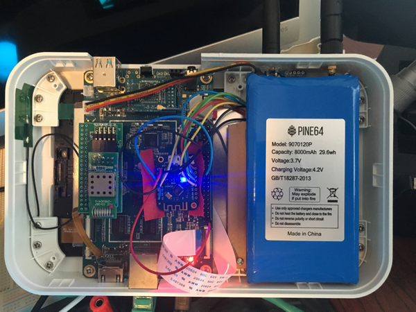
There’s actually a ZWave module in there too, but only because it came with my Kickstarter Bundle. I’m not actually using it yet.
Now, how did I get that slick looking dashboard of all my sensor data on there? Well, that’s actually the easiest part of the software build, so let’s get to the software!
The Software
I’ll go through the software I built in the same order as the hardware, just for consistency’s sake. Fell free to jump around to the parts that interest you the most.
The WiFi Sensor
Programming the Particle Photons is super easy using their web-based development environment. They have a Desktop version too, based on Atom, but I had regular problems with it so I stuck to the on-line one. One of the few drawbacks to Particle is that they expect everything to go through their cloud, but their cloud has no way of storing and analyzing data. A rather large weakness, if you ask me. But even if it didn’t, I’d have had to do things this way because, as stated earlier, I didn’t want to do a cloud-first architecture. I wanted the edge device to collect the data. I wanted to connect to a private WiFi network (served up by the edge device itself) and send all my data there.
It turns out that the first thing a Particle Photon always tries to do is contact the Particle Cloud. If it can’t, then things get weird. So the very first thing I had to do was tell it to please stop doing that!
Particle.disconnect();
WiFi.connect();
That stops that! And then connects me to my private WiFi. (You have to configure this via a USB connection to your Photon!).
Here’s all the code, and I can then go through it in more detail:
// This #include statement was automatically added by the Particle IDE.
#include <HttpClient.h>
// This #include statement was automatically added by the Particle IDE.
#include <Adafruit_TSL2561_U.h>
#include "Adafruit_Sensor.h"
#include "Adafruit_BME280.h"
#define SEALEVELPRESSURE_HPA (1013.25)
#define TELEGRAF_HOST "192.168.3.1"
#define TELEGRAF_PORT 1619
#define temp(x) String(x)

//the two sensors
Adafruit_BME280 bme;
Adafruit_TSL2561_Unified tsl = Adafruit_TSL2561_Unified(TSL2561_ADDR_FLOAT, 12345);

// some variables
double temperature = 0.00;
double pressure = 0.00;
double altitude = 0.00;
double humidity = 0.00;
uint16_t broadband = 0;
uint16_t infrared = 0;
int lux = 0;
String myID = System.deviceID();
String myName = "DemoKit3";
bool bme_config = true;
bool tsl_config = true;

// http stuff
http_request_t request;
http_response_t response;
HttpClient http;

SYSTEM_MODE(SEMI_AUTOMATIC);

int led = D7;

void setup() {
    delay(2000);
    Serial.begin(115200);
    Serial.println("No Cloud! Not using Particle.");
    Particle.disconnect();
    delay(2000);
    Serial.print("Connecting to WiFi ... ");
// this is all debug stuff that helped me get the WiFi working properly
    if(WiFi.hasCredentials()){
        Serial.println("Found credentials");
        WiFiAccessPoint ap[5];
        int found = WiFi.getCredentials(ap, 5);
        for (int i = 0; i < found; i++) {
            Serial.print("ssid: ");
            Serial.println(ap[i].ssid);
// security is one of WLAN_SEC_UNSEC, WLAN_SEC_WEP, WLAN_SEC_WPA, WLAN_SEC_WPA2, WLAN_SEC_WPA_ENTERPRISE, WLAN_SEC_WPA2_ENTERPRISE
            Serial.print("security: ");
            Serial.println(ap[i].security);
// cipher is one of WLAN_CIPHER_AES, WLAN_CIPHER_TKIP or WLAN_CIPHER_AES_TKIP
            Serial.print("cipher: ");
            Serial.println(ap[i].cipher);
        }
    }
    delay(2000);
    WiFi.connect();
    Serial.println("Starting up...");
    request.hostname = TELEGRAF_HOST;
    request.port = TELEGRAF_PORT;
    request.path = "/particle";
    int tryInit = 0;
// sometimes the BME sensor takes a while to get figured out.
    while (!bme.begin()) {
        Serial.println("Could not find a valid BME280 sensor, check wiring!");
        delay(3000);
        if(++tryInit > 9){
            bme_config = false;
            break;
        }
    }
    tryInit = 0;
/* Initialise the sensor */
    while(!tsl.begin()){
        Serial.print("Ooops, no TSL2561 detected ... Check your wiring or I2C ADDR!");
        delay(3000);
        if(++tryInit > 9){
            tsl_config = false;
            break;
        }
    }
/* Setup the sensor gain and integration time */
    if(tsl_config){
        configureSensor();
    }
    Serial.print("Device ID: ");
    Serial.println(myID);
// get a couple of readings to make sure …
    getReadings();
    delay(2000);
    getReadings();
/* Display some basic information on this sensor */
    displaySensorDetails();
/* We're ready to go! */
}

void loop() {
    getReadings();
    double fTemp = temperature * 9/5 + 32;
    Serial.print("My IP: ");Serial.println(WiFi.localIP());
    if(myName != "" ){
// begin http post remove for particle cloud publish
        http_header_t headers[] = {
          {"Accept", "*/*"},
          {"User-agent", "Particle HttpClient"},
          {NULL, NULL}
        };
        time_t time = Time.now();
        Time.format(time, TIME_FORMAT_ISO8601_FULL);
        int rssi = WiFi.RSSI();
        String data = String::format("{\"event\": \"iot_sensor\", \"data\": { \"tags\" : {\"id\": \"%s\", \"location\": \"%s\"}, \"values\": {\"RSSI\": %d, \"temp_c\": %f, \"temp_f\": %f, \"humidity\": %f, \"pressure\": %f, \"altitude\": %f, \"broadband\": %d, \"infrared\": %d, \"lux\": %d}}, \"ttl\": 60, \"coreid\": \"%s\", \"name\": \"sensor\", \"measurement\": \"iot_data\"}", myID.c_str(), myName.c_str(), rssi, temperature, fTemp, humidity, pressure, altitude, broadband, infrared, lux, myID.c_str());
        request.body = data;
        http.post(request, response, headers);
        Serial.print("Application>\tResponse status: ");
        Serial.println(response.status);
        Serial.print("Application>\tHTTP Response Body: ");
        Serial.println(response.body);
// end http post.
        delay(1000);
    }
}

/* Read the sensors */
void getReadings(){
    if(bme_config){
        temperature = bme.readTemperature();
        pressure = bme.readPressure() / 100.0F;
        altitude = bme.readAltitude(SEALEVELPRESSURE_HPA);
        humidity = bme.readHumidity();
    }
    if(tsl_config){
        sensors_event_t event;
        tsl.getEvent(&event);
/* Display the results (light is measured in lux) */
        if (event.light){
            lux = event.light;
        } else {
/* If event.light = 0 lux the sensor is probably saturated
and no reliable data could be generated! */
           lux = -1;
        }
/* Populate broadband and infrared with the latest values */
        tsl.getLuminosity (&broadband, &infrared);
    }
}

// Open a serial terminal and see the device name printed out
void handler(const char *topic, const char *data) {
    Serial.println("received " + String(topic) + ": " + String(data));
    myName = String(data);
}

int setLoc(String loc){
    myName = loc;
    return 1;
}

void configureSensor(void) {
/* You can also manually set the gain or enable auto-gain support */
// tsl.setGain(TSL2561_GAIN_1X); /* No gain ... use in bright light to avoid sensor saturation */
// tsl.setGain(TSL2561_GAIN_16X); /* 16x gain ... use in low light to boost sensitivity */
    tsl.enableAutoRange(true); /* Auto-gain ... switches automatically between 1x and 16x */

/* Changing the integration time gives you better sensor resolution (402ms = 16-bit data) */
    tsl.setIntegrationTime(TSL2561_INTEGRATIONTIME_13MS); /* fast but low resolution */
// tsl.setIntegrationTime(TSL2561_INTEGRATIONTIME_101MS); /* medium resolution and speed */
// tsl.setIntegrationTime(TSL2561_INTEGRATIONTIME_402MS); /* 16-bit data but slowest conversions */

/* Update these values depending on what you've set above! */
    Serial.println("------------------------------------");
    Serial.print ("Gain: "); Serial.println("Auto");
    Serial.print ("Timing: "); Serial.println("13 ms");
    Serial.println("------------------------------------");
}

void displaySensorDetails(void) {
    if(tsl_config){
        sensor_t sensor;
        tsl.getSensor(&sensor);
        Serial.println("------------------------------------");
        Serial.print ("Sensor: "); Serial.println(sensor.name);
        Serial.print ("Driver Ver: "); Serial.println(sensor.version);
        Serial.print ("Unique ID: "); Serial.println(sensor.sensor_id);
        Serial.print ("Max Value: "); Serial.print(sensor.max_value); Serial.println(" lux");
        Serial.print ("Min Value: "); Serial.print(sensor.min_value); Serial.println(" lux");
        Serial.print ("Resolution: "); Serial.print(sensor.resolution); Serial.println(" lux");
        Serial.println("---------------------------------reading_time: 37 minutes
---");
        Serial.println("");
        delay(500);
    }
}
Pretty straightforward. Initialize the sensors (and try a few times). If initialization fails, make sure to handle that as well. I used the bee_config and tsl_config booleans for that. Then read sensor data every second, and post it to the InfluxDB server in a JSON object. I’m actually re-using the Particle Plugin for Telegraf that I wrote, just because I could. I actually wrote the docs over at Particle.io for the InfluxDB/Particle integration (because I also wrote the integration, of course) so feel free to take a look at that if you’d like.
I now have a Particle Photon posting temperature (ºC and ºF), atmospheric pressure, humidity, infrared light, visible light, and lux to my edge device every second. Well, I would if I had an edge device built. That’s coming.
The BLE CO2 Sensor
As I said earlier, this one was a bit trickier. I could have programmed this with Arduino, and at first I did. But Arduino just isn’t up to the task with this sensor. That’s because the sensor’s I2C occasionally locks up, and when that happens in Arduino-land, you’re pretty much stuck. You have to restart the board. That’s fine, I guess, but when it happens every 30 seconds, it makes data collection rather unreliable. So I used embedded C on mBed instead. There are also two sides to this sensor. One was the actual sensor code that runs on the nRF52DK board. The other was the code to run on the Edge device to connect over bluetooth and get the data. So let’s start with the device-code. First, I had to define a BLE GATT Characteristic for the CO2 value, so I did that:
#ifndef __K30_SERVICE_H__
#define __K30_SERVICE_H__

class K30Service {
public: const static uint16_t K30_SERVICE_UUID = 0xA000;
const static uint16_t K30_VALUE_CHARACTERISTIC_UUID = 0xA001;

K30Service(BLEDevice &_ble, float k30Initial) :
ble(_ble), k30Value(K30_VALUE_CHARACTERISTIC_UUID, &k30Initial, GattCharacteristic::BLE_GATT_CHAR_PROPERTIES_NOTIFY) {
  GattCharacteristic *charTable[] = {&k30Value};
  GattService k30Service(K30Service::K30_SERVICE_UUID, charTable, sizeof(charTable) / sizeof(GattCharacteristic *));
  ble.addService(k30Service);
}

void updateK30Value(float newValue) {
  ble.updateCharacteristicValue(k30Value.getValueHandle(), (uint8_t *)&newValue, sizeof(float));
}
private: BLEDevice &ble; ReadOnlyGattCharacteristic k30Value; };

#endif
That’s our GATT Service so that whenever we call it, we get the updated CO2 value from the sensor. Now the code to get the sensor data. Remember, this is I2C code in C. I’m going to go through it in sections to make it more clear what I’m doing.
/**
  Copyright (c) 2018 David G. Simmons
  Licensed under the Apache License, Version 2.0 (the "License");
  you may not use this file except in compliance with the License.
  http://www.apache.org/licenses/LICENSE-2.0
**/
#include <events/mbed_events.h>
#include <mbed.h>
#include "ble/BLE.h"
#include "ble/Gap.h"
#include "k30.h"
#include "nrf_nvic.h"
The k30.h is the code above defining the GATT Service. Next, let’s get all the variable, etc. defined.
DigitalOut led1(LED1);
DigitalOut led2(LED2);
DigitalOut led3(LED3);
DigitalOut led4(LED4);
//I2C i2c(p24 , p25);
// Standard I2C pins on the nRF52. But you can use any pins you want really.
I2C i2c(p26, p27);
const int addr = 0xD0;
static int failures = 0;
const static char DEVICE_NAME[] = "CO2Sensor";
static const uint16_t uuid16_list[] = {K30Service::K30_SERVICE_UUID};
static float co2Level = 50.0;
static K30Service* k30ServicePtr;
static EventQueue eventQueue(EVENTS_EVENT_SIZE);
The nRF52DK has 4 service LEDs on board. I wanted them to go around and around in sequence because I could. Oh, and they should also be able to go backwards. Don’t ask how long I spent getting the timing right so it looked nice.
void lightsFwd(){
  led1 = !led1;
  wait(.15);
  led2 = !led2;
  wait(.15);
  led4 = !led4;
  wait(.15);
  led3 = !led3;
  wait(.15);
}

void lightsRev(){
  led1 = !led1;
  wait(.15);
  led3 = !led3;
  wait(.15);
  led4 = !led4;
  wait(.15);
  led2 = !led2;
  wait(.15);
}
Now we get to the interesting bit: actually reading the sensor! This is pretty straightforward I2C. The SenseAir Docs have all the details like the I2C address, the commands, etc. so that was already done for me. If you’re using Arduino, there’s actually a complete Arduino sketch that has this as well.
void readSensor(){
  // register values
  char cmd[4] = {0x22, 0x00, 0x08, 0x2A};
  int ack = i2c.write(addr, cmd, 4);
  wait(0.5);
  char readBuff[4];
  i2c.read(addr, readBuff, 4, false);
  int high = readBuff[1]; //high byte for value is 4th byte in packet in the packet
  int low = readBuff[2]; //low byte for value is 5th byte in the packet
  float CO2 = high*256 + low; //Combine high byte and low byte with this formula to get value
  char sum = readBuff[0] + readBuff[1] + readBuff[2]; //Byte addition utilizes overflow
  if (sum == readBuff[3] & ack == 0){
    //pc.printf("CO2 value = %fn", CO2);
    k30ServicePtr->updateK30Value(CO2);
    if(failures > 0){
      failures--;
    }
  } else {
    //pc.printf("** Sensor Failure **n");
    failures++;
    CO2 = -1;
    k30ServicePtr->updateK30Value(CO2);
    if(failures > 5){ // Keep track of the number of failures. If more than 5, reboot the board.
      i2c.stop();
      for(int x = 0; x < 10; x++){
        lightsRev();
      }
      NVIC_SystemReset();
    }
  }
}

void disconnectionCallback(const Gap::DisconnectionCallbackParams_t *params)
{
  //pc.printf("Disconnected!n");
  BLE::Instance().gap().startAdvertising();
}
You’ll notice a few things in there. First, the sensor has a checksum byte, and the sensor does, indeed, sometimes fail this test. I keep track of the number of failures in. a row. If I get more than 5 failures in a row, I concluded that the sensor is having trouble, so I reboot the board and start over. After a long bit of trial and error, I found that this is a suitable solution.
The rest of this code is pretty standard boilerplate for BLE connections, etc. and indeed mostly came out of the mBed example programs.
void updateSensorValue() {
  lightsFwd();
  readSensor();
  wait(1.5);
  lightsFwd();
  wait(1.5);
}

void connectionCallback(const Gap::ConnectionCallbackParams_t *params) {
  // pc.printf("Connected!n");
  BLE::Instance().gap().stopAdvertising();
  eventQueue.call(updateSensorValue);
}

void sensorCallback(void) {
  BLE &ble = BLE::Instance();
  if (ble.gap().getState().connected) {
    eventQueue.call(updateSensorValue);
  } else {
    lightsFwd();
  }
}

void onBleInitError(BLE &ble, ble_error_t error) {

}

void printMacAddress(){
  Gap::AddressType_t addr_type;
  Gap::Address_t address;
  BLE::Instance().gap().getAddress(&addr_type, address);
  //pc.printf("DEVICE MAC ADDRESS: ");
  for (int i = 5; i >= 1; i--){
    // printf("%02x:", address[i]);
  }
  //pc.printf("%02xrn", address[0]);
}

void bleInitComplete(BLE::InitializationCompleteCallbackContext *params) {
  BLE& ble = params->ble;
  ble_error_t error = params->error;
  if (error != BLE_ERROR_NONE) {
    onBleInitError(ble, error);
    return;
  }
  if(ble.getInstanceID() != BLE::DEFAULT_INSTANCE) {
    return;
  }

  ble.gap().onDisconnection(disconnectionCallback);
  ble.gap().onConnection(connectionCallback);
  k30ServicePtr = new K30Service(ble, co2Level);

  ble.gap().accumulateAdvertisingPayload(GapAdvertisingData::BREDR_NOT_SUPPORTED | GapAdvertisingData::LE_GENERAL_DISCOVERABLE);
  ble.gap().accumulateAdvertisingPayload(GapAdvertisingData::COMPLETE_LIST_16BIT_SERVICE_IDS, (uint8_t *) uuid16_list, sizeof(uuid16_list));
  ble.gap().accumulateAdvertisingPayload(GapAdvertisingData::COMPLETE_LOCAL_NAME, (uint8_t *) DEVICE_NAME, sizeof(DEVICE_NAME));
  ble.gap().setAdvertisingType(GapAdvertisingParams::ADV_CONNECTABLE_UNDIRECTED);
  ble.gap().setAdvertisingInterval(1000);
  ble.gap().startAdvertising();
}

void scheduleBleEventsProcessing(BLE::OnEventsToProcessCallbackContext* context) {
  BLE &ble = BLE::Instance();
  eventQueue.call(Callback<void()>(&ble, &BLE::processEvents));
}

int main() {
  eventQueue.call_every(1000, sensorCallback);
  BLE &ble = BLE::Instance();
  ble.onEventsToProcess(scheduleBleEventsProcessing);
  ble.init(bleInitComplete);
  eventQueue.dispatch_forever();
  return 0;
}
So that reads the CO2 value from the sensor every (what looks like) second — at least the callback gets called every second. But in that callback I run the lights around, which takes an additional ~3.25 seconds. And there’s a reason for that. If I were to simply read the sensor every second, I would get duplicate results, and a lot more failures. That’s because the sensor itself only updates its registers every 2 seconds or so. And if you try to read while it’s updating them, it hangs. So this was my compromise for sensor reliability. Seems to have been successful.
Now, as I said, I still had to read the data via bluetooth from the Edge Device, so I needed to write something to handle that. The most effective way to get to your Bluetooth device from Linux is by using gatttool, but that’s basically a command-line tool. I’m pretty sure that I could have written some more C code to access the BLE device directly, but I decided to write a small program in Go to simply use gatttool to do it. Again, I’ll go through this in sections for you.
We start with some standard Go imports and definitions:
package main

import (
  "os/exec"
  "strings"
  "bufio"
  "fmt"
  "encoding/binary"
  "encoding/hex"
  "log"
  "math"
  "os"
  "bytes"
  "time"
  "strconv"
)

var (
  colonByte = []byte(":")
  spaceByte = []byte(" ")
)

var (
  Trace *log.Logger
  Info *log.Logger
  Warning *log.Logger
  Error *log.Logger
)

const timeout = 10 * time.Second

func Float32frombytes(bytes []byte) float32 {
  bits := binary.LittleEndian.Uint32(bytes)
  float := math.Float32frombits(bits)
  return float
}
func Float32bytes(float float32) []byte {
  bits := math.Float32bits(float)
  bytes := make([]byte, 4) binary.LittleEndian.PutUint32(bytes, bits)
  return bytes
}
The only really interesting bits there are the conversion of a bunch of bytes to a Float32. Turns out when you read from gatttool what you get back is an array of raw bytes. Since I was writing a Float to BLE from the device, I have to convert those 4 bytes back to a Float. Thanks to Google, I found a way to do that.
func postResults(result string) {
  var out bytes.Buffer
  var stderr bytes.Buffer
  cmdProc := exec.Command("/usr/bin/curl", "-i", "-XPOST", "http://localhost:8186/write", "--data-binary", result)
  cmdProc.Stdout = &out
  cmdProc.Stderr = &stderr
  err := cmdProc.Run()
  defer cmdProc.Wait()
  if err != nil {
    Error.Println(err)
    return
  }
  Info.Println("Result: " + out.String())
}
Ok, I know, you’re saying WTF?? But yea, I used curl to post the data to the database. It seemed like a good idea at the time. I’ll re-write it using the InfluxDB Go Library someday but I was in a hurry.
This next bit was fun.
func runCommand(macAddr string) {
  input := make(chan []byte, 1)
  argString := string("-b " + macAddr + " -t random --char-write-req --handle=0x000f --value=0100 --listen")
  args := strings.Fields(argString)
  cmdString := "/usr/local/bin/gatttool"
  cmd := exec.Command(cmdString, args...)
  Info.Println("Running: ", cmdString, args)
  cmdOut, _ := cmd.StdoutPipe()
  cmd.Start()
  defer cmd.Wait()
  defer cmdOut.Close()
  reader := bufio.NewReader(cmdOut)
  go func() {
    buff, _ := reader.ReadBytes('n')
    Trace.Println(string(buff))
    input <- buff
  }()
  select {
    case <-time.After(timeout):
      Error.Println(" GATTTOOL timed out. Sensor nbot on?")
      cmd.Process.Kill()
      return
    case i := <-input:
      res := bytes.Split(i, spaceByte);
      //fmt.Println("Length ", len(res))
      if(len(res) < 4 ) {
        Error.Println("Unexpected return from Gatttool")
        cmd.Process.Kill()
        return
      }
  }
  for 1 > 0 {
    go func() {
      buff, _ := reader.ReadBytes('n')
      Trace.Println(string(buff))
      input <- buff
    }()
    select {
      case <-time.After(timeout):
        Warning.Println("timed out")
        cmd.Process.Kill()
        return
      case i := <-input:
        Trace.Println(string(i))
        result := bytes.Split(i, colonByte)
        fd := bytes.Fields(result[1])
        reading := make([]byte, 4)
        for x := 0; x < len(fd); x++ {
          data, err := hex.DecodeString(string(fd[x]))
          if err != nil {
            panic(err)
          }
          reading[x] = data[0]
        }
        float := Float32frombytes(reading)
        if(float < 1){
          Info.Println("Failed Sensor")
          continue;
        } else {
          st := "k30_reader,sensor=k30_co2 co2=" + strconv.Itoa(int(float))
          Trace.Println(st)
          postResults(st)
        }
    }
  }
}
Now that looks like a lot, and looks confusing, but here’s what it basically does. You see, it can open GATTTOOL, but if the device on the other end either isn’t there, or has disconnected, then things break. So I have to timeout on the gatttool command and retry if that happens (which, if you remember the sensor code, it’s for sure going to if the sensor locks up). So there’s a whole bunch of checks to make sure that we get connected, that we get a result, and that the result is at least nominally rational before we go and try to post it to the database. Just believe me when I say that a lot of trial and error and failures went into making this robust. And it is robust. It has run flawlessly for over a month now, 24/7, without problems.
func Init(){
  file, err := os.OpenFile("/var/log/blueCO2.log", os.O_CREATE|os.O_WRONLY|os.O_APPEND, 0666)
  if err != nil {
    fmt.Println("Failed to open log file", err)
  }
  Trace = log.New(file,"TRACE: ", log.Ldate|log.Ltime|log.Lshortfile)
  Info = log.New(file, "INFO: ", log.Ldate|log.Ltime|log.Lshortfile)
  Warning = log.New(file, "WARNING: “, log.Ldate|log.Ltime|log.Lshortfile)
  Error = log.New(file, "ERROR: “, log.Ldate|log.Ltime|log.Lshortfile)
}
func main() {
  Init()
  myArgs := os.Args[1:]
  macAddr := myArgs[0]
  if(len(myArgs) < 1){
    Error.Println("No BLE Device Address Suplied, Exiting.")
    return
  }
  for 1>0 {
    runCommand(macAddr)
  }
}
Again, fairly straightforward. Just set up some logging functionality, and then run forever. Obviously you have to pass the program the MAC address of the BLE device you want to connect to, but that’s the only thing you need.
So that’s the CO2 sensor, both from the sensor side and from the Edge Device side. whew
The LoRA Sensors
These are actually two separate sensors, as you know, but I’m going to save us all a little bit of time by combining them since they share a ton of code. Once again, I’ll go through the code in pieces to make it easier. The Radiation Sensor came with a nice little Arduino Library, so Just used that.
#include <ESP8266WiFi.h>
#include "RadiationWatch.h"
#include <SPI.h>
#include <RH_RF95.h>
#include <Wire.h>

// for WEMOs D1 Mini
#define RFM95_CS D0
#define RFM95_INT D8
#define RFM95_RST D3
// Where to send packets to!
#define DEST_ADDRESS 1
// change addresses for each client board, any number :)
#define MY_ADDRESS 2
// Wemos D1 Mini pins
RadiationWatch radiationWatch(D1, D2);

// Change to 434.0 or other frequency, must match RX's freq!
#define RF95_FREQ 434.0

// Blinky on send
#define STATUS_LED D4
// Singleton instance of the radio driver
RH_RF95 rf95(RFM95_CS, RFM95_INT);
int16_t packetnum = 0; // packet counter, we increment per xmission
That’s the defines for the Radiation sensor. Now here’s the stuff for the Melexis Temperature sensor (again, there’s an Arduino Library out there which made it easy).
#include <ESP8266WiFi.h>
#include <Adafruit_MLX90614.h>
#include <SPI.h>
#include <RH_RF95.h>
#include <Wire.h>

// for WEMOs D1 Mini
#define RFM95_CS D0
#define RFM95_INT D8
#define RFM95_RST D3

#define GREEN_LED D4

// Change to 434.0 or other frequency, must match RX's freq!
#define RF95_FREQ 434.0

// Blinky on send
#define LED LED_BUILTIN
// Where to send packets to!
#define DEST_ADDRESS 1
// change addresses for each client board, any number :)
#define MY_ADDRESS 3
// Singleton instance of the radio driver
RH_RF95 rf95(RFM95_CS, RFM95_INT);
// for the sensor
Adafruit_MLX90614 mlx = Adafruit_MLX90614();
Then they both do the same setup function:
void setup() {
  pinMode(STATUS_LED, OUTPUT);
  Serial.begin(115200);
  while (!Serial) {
    delay(1);
  }
  // we're not using the Wemos WiFi.
  WiFi.mode(WIFI_OFF);
  delay(1000);
  pinMode(RFM95_RST, OUTPUT);
  delay(500);
  digitalWrite(RFM95_RST, HIGH);
  delay(500);
  Serial.println("LoRa Radiation TX!");
  // manual reset
  digitalWrite(RFM95_RST, LOW);
  delay(100);
  digitalWrite(RFM95_RST, HIGH);
  delay(100);

  while (!rf95.init()) {
    Serial.println("LoRa radio init failed");
    while (1);
  }
  Serial.println("LoRa radio init OK!"); // Defaults after init are 434.0MHz, modulation GFSK_Rb250Fd250, +13dbM
  if (!rf95.setFrequency(RF95_FREQ)) {
    Serial.println("setFrequency failed");
    while (1);
  }
  Serial.print("Set Freq to: "); Serial.println(RF95_FREQ);
  // Defaults after init are 434.0MHz, 13dBm, Bw = 125 kHz, Cr = 4/5, Sf = 128chips/symbol, CRC on
  // The default transmitter power is 13dBm, using PA_BOOST.
  // If you are using RFM95/96/97/98 modules which uses the PA_BOOST transmitter pin, then
  // you can set transmitter powers from 5 to 23 dBm:
  rf95.setTxPower(23, false);
  Serial.println("Starting sensor ... ");
}
The Radiation sensor has to register some callbacks, and define those callbacks:
radiationWatch.setup();
// Register the callbacks.
radiationWatch.registerRadiationCallback(&onRadiation);
radiationWatch.registerNoiseCallback(&onNoise);
Serial.println("Callbacks Registered.");
digitalWrite(STATUS_LED, LOW);

// it’s a sensitive little bugger
void onNoise() {
  Serial.println("Argh, noise, please stop moving");
}

void onRadiation() {
  digitalWrite(STATUS_LED, HIGH);
  Serial.println("Reading Radiation...");
  char buf[RH_RF95_MAX_MESSAGE_LEN];
  uint8_t len = sizeof(buf);
  Serial.println("A wild gamma ray appeared");
  double rad = radiationWatch.uSvh();
  double var = radiationWatch.uSvhError();
  double dose = radiationWatch.cpm();
  double er = radiationWatch.uSvh();
  double coef = radiationWatch.uSvhError();
  Serial.print(" Dose: "); Serial.println(dose);
  Serial.print(rad);
  Serial.print(" uSv/h +/- ");
  Serial.println(var);
  // Message format is "R,gamma_ray_strength,dose" because the receiver is ALSO getting
  // data from a temp sensor. Could also send the variation, error and error coefficient.
  sprintf(buf, "%s,%s,%s", "R", String(rad).c_str(), String(dose).c_str());
  sendMessage(buf, len);
  digitalWrite(STATUS_LED, LOW);
}
I defined my own message format because I had to differentiate between the two sensors, and I still had to keep the message size very small to keep the radio board from breaking it up into separate packets.
Initializing the Melexis sensor was a single call to
mlx.begin()
It then just loops forever reading and sending data:
double ambTempC = mlx.readAmbientTempC();
double objTempC = mlx.readObjectTempC();

// Message format is "T,AmbientTemp,ObjectTemp" because the receiver is ALSO getting
// data from a radiation sensor.
Serial.print("Amb: "); Serial.print(ambTempC);
Serial.print(" Obj: " ); Serial.println(objTempC);
sprintf(buf, "%s,%s,%s", "T", String(ambTempC).c_str(), String(objTempC).c_str());
digitalWrite(LED, HIGH);
digitalWrite(GREEN_LED, HIGH);
Both sensors have the exact same message sending/reply functions:
int sendMessage(char* buf, uint8_t len) {
  Serial.println("Transmitting..."); // Send a message to rf95_server
  char radiopacket[20];
  for (int x = 0; x < 20; x++) {
    if (x == len || x > len) {
      radiopacket[x] = '0';
    }
    radiopacket[x] = buf[x];
  }
  itoa(packetnum++, radiopacket + 13, 10);
  Serial.print("Sending "); Serial.println(radiopacket);
  radiopacket[19] = 0;
  Serial.println("Sending...");
  delay(10);
  rf95.send((uint8_t *)radiopacket, 20);
  Serial.println("Waiting for packet to complete...");
  delay(10);
  rf95.waitPacketSent();
  // Now wait for a reply
  waitReply();
}
void waitReply() {
  uint8_t buf[RH_RF95_MAX_MESSAGE_LEN];
  uint8_t len = sizeof(buf);
  Serial.println("Waiting for reply...");
  if (rf95.waitAvailableTimeout(10000)) {
  // Should be a reply message for us now
    if (rf95.recv(buf, &len)) {
      Serial.print("Got reply: ");
      Serial.println((char*)buf);
      Serial.print("RSSI: ");
      Serial.println(rf95.lastRssi(), DEC);
    }
    else {
      Serial.println("Receive failed");
    }
  } else {
    Serial.println("No reply, is there a listener around?");
  }
}
Technically I don’t have to wait for a reply, but I do, just for debugging purposes. Now, as you’d expect, there is some similar code that run on the Wemos tucked inside the Edge Collector, and it is really simple, and very similar. It just reads messages from the radio, formats them a bit, and writes them out to the serial port.
#include <SPI.h>
#include <RH_RF95.h>
#include <ESP8266WiFi.h>
// Wemos D1 Mini ...
#define RFM95_CS D1
#define RFM95_IRQ D2
#define RFM95_RST D3
//
// This is the receiver, so it receives from anyone, others send to this address.
#define MY_ADDRESS 1

// Change to 434.0 or other frequency, must match RX's freq!
#define RF95_FREQ 434.0
// Singleton instance of the radio driver
RH_RF95 rf95(RFM95_CS, RFM95_IRQ);
// Blinky on receipt
#define LED LED_BUILTIN

void setup() {
  Serial.begin(115200)
  while (!Serial); {
    delay(1);
  }
  delay(100);
  // we're not using the Wemos WiFi.
  WiFi.mode(WIFI_OFF);
  Serial.println("LoRa RXer!");
  pinMode(LED, OUTPUT);
  pinMode(RFM95_RST, OUTPUT);
  digitalWrite(RFM95_RST, HIGH);
  // manual reset
  digitalWrite(RFM95_RST, LOW);
  delay(100);
  digitalWrite(RFM95_RST, HIGH);
  delay(100);

  while (!rf95.init()) {
    Serial.println("LoRa radio init failed");
    while (1);
  }
  Serial.println("LoRa radio init OK!");

  // Defaults after init are 434.0MHz, modulation GFSK_Rb250Fd250, +13dbM
  if (!rf95.setFrequency(RF95_FREQ)) {
    Serial.println("setFrequency failed");
    while (1);
  }
  Serial.print("Set Freq to: "); Serial.println(RF95_FREQ);
  // The default transmitter power is 13dBm, using PA_BOOST.
  // If you are using RFM95/96/97/98 modules which uses the PA_BOOST transmitter pin, then
  // you can set transmitter powers from 5 to 23 dBm:
  rf95.setTxPower(23, false);
}
The loop simply waits for a message, and then formats it:
void loop(){
  if (rf95.available()) {
  // Should be a message for us now
  uint8_t buf[RH_RF95_MAX_MESSAGE_LEN];
  uint8_t len = sizeof(buf);
  String msgBuff = "iot_sensor,recv_from=LoRa ";
  if (rf95.recv(buf, &len)) {
    digitalWrite(LED, HIGH);
    char *p = (char *)buf;
    char *str;
    char* strAr[3];
    int x = 0;
    // incoming message format: T|R,reading1,reading2
    while ((str = strtok_r(p, ",", &p)) != NULL) {// delimiter is the comma
      strAr[x++] = str;
    }
    String mType = String(strAr[0]);
    double reading1 = String(strAr[1]).toFloat();
    double reading2 = String(strAr[2]).toFloat();
    if (mType == "T") {
      msgBuff += "AmbTempC=";
      msgBuff += String(reading1);
      msgBuff += ",ObjTempC=";
      msgBuff += String(reading2);
      msgBuff += ",AmbTempF=";
      msgBuff += String((reading1 CONTRIBUTING.rst LICENSE MANIFEST.in README.rst THANKS build dist docs output pelican pelican.egg-info posts_processed posts_to_process process.sh pyproject.toml requirements samples setup.cfg setup.py tasks.py tox.ini 1.8) + 32);
      msgBuff += ",ObjTempF=";
      msgBuff += String((reading2 CONTRIBUTING.rst LICENSE MANIFEST.in README.rst THANKS build dist docs output pelican pelican.egg-info posts_processed posts_to_process process.sh pyproject.toml requirements samples setup.cfg setup.py tasks.py tox.ini 1.8) + 32);
    } else {
      msgBuff += "gamma_ray=";
      msgBuff += String(reading1);
      msgBuff += ",dose=";
      msgBuff += String(reading2);
    }
    msgBuff += ",RSSI=";
    msgBuff += String(rf95.lastRssi());
    msgBuff += ".0";
    Serial.println(msgBuff);
    // Send a simple reply
    uint8_t data[] = "Roger that!";
    rf95.send(data, sizeof(data));
    rf95.waitPacketSent();
    digitalWrite(LED, LOW);
  } else {
     Serial.println("Receive failed");
  }
}
You’re probably saying “But isn’t all that Serial line chatter going to mess with the database?” and you’d be right, except I wrote some Go code on the Edge Device to read the data from the Serial port and deal with it.
package main
import (
  "os/exec"
  "fmt"
  "bufio"
  "syscall"
  "log"
  "os"
  "bytes"
  "time"
  "strings"
)
var (
  colonByte = []byte(":")
  spaceByte = []byte(" ")
)

var (
  Trace *log.Logger
  Info *log.Logger
  Warning *log.Logger
  Error *log.Logger
)

const timeout = 10 * time.Second
func postResults(result string) {
  var out bytes.Buffer
  var stderr bytes.Buffer
  cmdProc := exec.Command("/usr/bin/curl", "-i", "-XPOST", "http://localhost:8186/write", "--data-binary", result)
  cmdProc.Stdout = &out
  cmdProc.Stderr = &stderr
  err := cmdProc.Run()
  if err != nil {
    Error.Println(err)
    return
  }
  fmt.Println("Result: " + out.String())
}
func runPort() {
  tty, err := os.OpenFile("/dev/ttyS2", os.O_RDWR|syscall.O_NOCTTY, 0)
  if err != nil {
    log.Fatalf("Cannot open tty port: %vn", err)
  }
  defer tty.Close()
  for 1 > 0 {
    scanner := bufio.NewScanner(tty)
    for scanner.Scan() {
      result := scanner.Text()
      startsWith := strings.HasPrefix(result, "iot_sensor")
      if startsWith {
        postResults(result)
        fmt.Println(result)
      }
    }
    if err := scanner.Err(); err != nil {
      log.Fatal(err)
    }
  }
}
func Init(){
  file, err := os.OpenFile("/var/log/wemos.log", os.O_CREATE|os.O_WRONLY|os.O_APPEND, 0666)
  if err != nil {
    fmt.Println("Failed to open log file", err)
  }
  Trace = log.New(file,
    "TRACE: ",
    log.Ldate|log.Ltime|log.Lshortfile)
  Info = log.New(file,
    "INFO: ",
    log.Ldate|log.Ltime|log.Lshortfile)
  Warning = log.New(file,
    "WARNING: ",
    log.Ldate|log.Ltime|log.Lshortfile)
  Error = log.New(file,
    "ERROR: ",
    log.Ldate|log.Ltime|log.Lshortfile)
}

func main() {
  Init()
  for 1>0 {
    runPort()
  }
}
And yes, there’s probably a better way, but I already had the code from the other sensor and I was again in a hurry. So there you have it.
And that’s all the sensor code! You should now be able to build all the sensors that I built and have them run the same. But what you really came here for was the Edge Collection device! I know, that’s why I saved it until last. So let’s get to that!
Edge Collection Device
So, you’ve spent the $100 or so for all the parts for the Edge Collection device, and now you’re wondering how to actually build it. Welcome to the club! So was I. As it turns out — and Pine-64 doesn’t tell you this up front — but there is actually fairly limited support for the Touchscreen display. The one that they sell. Right. Apparently it works great with Android, but that really didn’t help me much. The version of Linux you pretty much have to use is called Armbian. Right, I’d never heard of it either. Before just diving in and installing it, I strongly suggest that you read and understand everything here. Really. I didn’t, and it was a fairly painful experience. That’s also because things like the Touchscreen driver wasn’t in the mainline then, which it is now.
Next thing was, of course, to get InfluxDB and the rest of the TICK stack installed. Luckily that is super easy — of course. Here’s the fastest and easiest way to do that:
curl -sL https://repos.influxdata.com/influxdb.key | sudo apt-key add -
source /etc/lsb-release
echo "deb https://repos.influxdata.com/${DISTRIB_ID,,} ${DISTRIB_CODENAME} stable" | sudo tee /etc/apt/sources.list.d/influxdb.list
That will add the following line to your sources.list.d/influxdb.list file:
deb https://repos.influxdata.com/ubuntu xenial stable
Which is what you want. Then run:
$ sudo apt-get update
$ sudo apt-get install influxdb chronograf telegraf kapacitor
and you’re all set! Now, all you have to do is make sure that the code for each of the sensors above is properly installed, and … you’re almost there.
You’ll want to install the Mosquito MQTT broker from Eclipse IoT, but luckily that’s as simple as apt-get install mosquito and you’re good to go.
Remember that I said you should read all of the Armbian docs? Right, if you did, then you’ll know that Bluetooth doesn’t actually work out of the box. So here’s how I solved that. I created a script, called ‘ble.sh’:
#! /bin/sh

/usr/sbin/rfkill list
/usr/local/bin/rtk_hciattach -n -s 115200 /dev/ttyS1 rtk_h5
/bin/hciconfig hci0 up
That will get the ble device setup done. But it has to be run every time your device reboots, so I created a SystemV service control for it
/lib/systemd/system/bluetooth-device.service
[Unit]
Description=Bring the BLE device online, if possible
After=network-online.target

[Service]
ExecStart=/bin/sh /usr/local/bin/ble.sh
Restart=on-failure

[Install]
WantedBy=multi-user.target
Now it gets run every time the device reboots and only after the network is up.
I actually wanted the whole box to be basically automatic, so I did a lot of other stuff as system services, like the Bluetooth reader Go script, the Serial Port Go script, etc. Those all start automatically at boot time as well, just so that there is basically zero user-intervention needed. I built this as a data appliance, so zero-configuration was a goal, and a feature.
If you bought the WiFi/BLE adapter — which you really should have — then you get 2 WiFi interfaces. I set one of them up as a private access point for local WiFi sensors and the other I left to join another WiFi network for data upload. Armbian comes with it’s own hostapd installed, so you can just use that to set up the Access Point. Use the wlan1 interface for the AP.
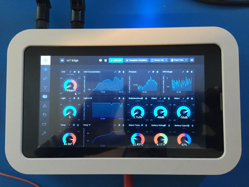
So now you have a box that has all the right parts, and should be able to have any and all of the sensors described above connect and log data. Here’s what the dashboard on mine looks like:
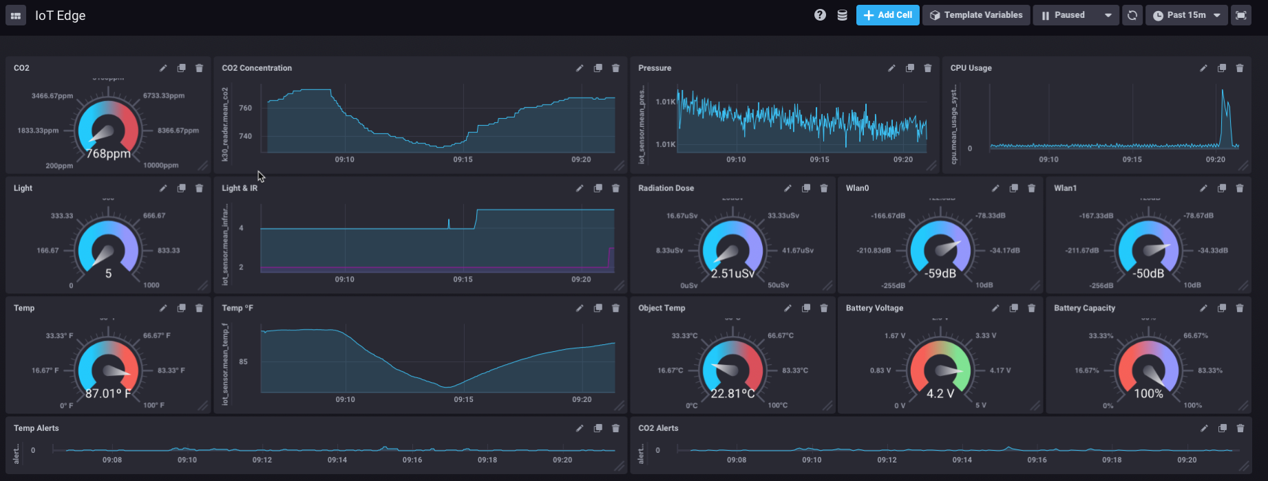
Pretty snappy! Now, there are a couple of dashboard elements on there that you won’t be able to get — at least out of the box. Those are the RSSI monitors and the battery monitor. That’s because those aren’t part of telegraf (yet). I wrote those collectors myself. You can get those from my GitHub fork of Telegraf here. It’s in the ‘IoTEdge’ branch. Just build that, and update your telegraf.conf file with the following:
[[inputs.linux_battery]]
# ## command for reading. If empty default path will be used:
# ## This can also be overridden with env variable, see README.
battstatus = "/sys/class/power_supply/battery/status"
battvoltage = "/sys/class/power_supply/battery/voltage_now"
battcurrent = "/sys/class/power_supply/battery/current_now"
battcapacity = "/sys/class/power_supply/battery/capacity"
batthealth = "/sys/class/power_supply/battery/health"
and
# # Collect wireless interface link quality metrics
[[inputs.linux_wireless]]
# ## file path for proc file. If empty default path will be used:
## /proc/net/wireless
# ## This can also be overridden with env variable, see README.
proc_net_wireless = "/proc/net/wireless"
# ## dump metrics with 0 values too
# dump_zeros = true
That will get you the stats on the battery/power and on any and all wireless interfaces installed. If you want to save yourself a ton of work, and want a dashboard that looks exactly like mine you’re in for a real treat. With the new Chronograf (v1.6) you can simply save this, and then import it and have an exact copy!
Ok, we’re almost there! The last thing was that I wanted this, as I said, to be ‘automatic’ so I didn’t want anyone to have to login, or launch the dashboard, etc. So first, I had to get rid of the login bit.
I installed ‘nodm’ as the default manager, which bypasses the login screen on boot up. That’s fairly simple. But now to make sure that the dashboard always comes up by default, at full-screen so there’s very little room for end-user shenanigan. You need to create a startup item for Chromium Browser:
demokit-2:/home/demo/.config# cat autostart/dashboard.desktop
[Desktop Entry]
Encoding=UTF-8
Version=0.9.4
Type=Application
Name=Chronograf Dashboard
Comment=dashboard
Exec=chromium-browser --incognito --kiosk http://localhost:8888/sources/1/dashboards/1#
OnlyShowIn=XFCE;
StartupNotify=false
Terminal=false
Hidden=false
I created a user ‘demo’ that has very limited permissions, and put this file in their .config/autostart directory. That kicks off Chrome browser, pointed directly at the dashboard, with no window decorations, so the user can’t exit the browser and have access to the user desktop. The only drawback to this is that you have to have an alternative method of logging in and controlling/configuring things. For that, I installed TightVNC — and enabled it under a different user I created. So there’s a ‘setup’ user that can login with TightVNC to do things like change the WiFi setup, etc. but the ‘demo’ user always gets the pre-defined dashboard.
Conclusion
That should be a great start on building this whole setup. I will admit that Armbian can be a bit fiddly and takes a fair amount of TLC to get it setup correctly. Getting the WiFi AP working, and connecting the other WiFi interface to an upstream internet connection is tough. The upstream WiFi has a nasty habit of just dropping off, or losing its default route, etc.
I have probably forgotten a bunch of little tweaks I made here and there to make things work smoothly, and where I have omitted things, I apologize. I undertook this project over the course of several months and am constantly making small improvements. It has been difficult to keep track of all the small changes made. If you find anything that is inaccurate, or needs updating, please contact me and let me know!
And finally, if you build one of these, I’d love to hear about it! Let me know what you built, and how you’re using it!
 English
 Deutsche
 Dutch
Dutch Español
 Français