
David G. Simmons
Tuesday, March 15, 2022
An Automated IoT Greenhouse with Camunda
Note: Originally published on DZone so don’t forget to give it some ❤️ over there!
Running this project
- Clone the repository
cdinto the project directory:- Deploy the
co2.bpmnprocess definition to your Camunda server cdinto thetask-workerdirectory:- run
go mod tidyto update thetask-workermodule - adjust all constant values in the
task-handler.gofile - run
go run task-handler.go
- run
- cd into the
arduino-codedirectory- open the
Greenhouse.inofile in the Arduino IDE - adjust all constant values in
Greenhouse.ino - deploy the Arduino code to your Arduino board
- open the
- Deploy the
- Have fun!
Review
If you’ve been following this (incredibly slow) project, then you’ve already been through part 1 and part 2 and have been wondering if part 3 would ever arrive. Well, here it is! This is the part where I pull together all the previous parts and actually deploy a Camunda BPMN-powered IoT Greenhouse!
Just to review a bit, I proposed building a greenhouse, monitored by some IoT sensors, that would then be entirely controlled by a Camunda BPMN process. The entire process would then control all aspects of the Greenhouse.
How it’s going
Previously I deployed a weather station that would monitor all the outdoor weather conditions so that I could correlate them to the readings from withing the greenhouse and decide things like if opening a window would help cool, or reduce humidity, inside. The Weather station has been up and running now for a number of months, and it was time to actually build the sensors and deploy them to the greenhouse.
Before anyone gets all excited, I did not, in fact, deploy a full-sized, or even a large, greenhouse to my yard (as much as I wanted to). Instead I started small with a desktop greenhouse (or what you might also call a terrarium).
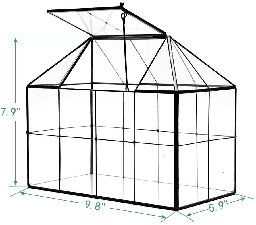
As you can see, it’s not all that large, but it does have a roof-panel that I can open and close, so it will do for the proof of concept here.
The sensors
In order to monitor the greenhouse I wanted to make sure that I had a number of sensors that could track the basic environmental conditions inside the greenhouse. I decided that the most important things to monitor were temperature, humidity, CO2 concentration, and soil moisture for the plants (more on the ‘plants’ later).
You may notice that these were largely the same sensors that I deployed outdoors (with the exception of the wind, rain and lightning sensors). That was not by chance, as I wanted to be able to correlate data between the pairs of indoor and outdoor sensors.
| Sensor | Measurement | Part URL | Cost |
|---|---|---|---|
| Soil Moisture | Soil Moisture | Sparkfun Soil Moisture Sensor | $5.95 |
| SCD30 | CO2, Temperature, Humidity | Adafruit SCD 30 Breakout | $58.95 |
I decided, after comparing the readings between several sensors that the SCD30’s temperature and humidity readings were accurate enough that I didn’t need to deploy a BME280 or other temperature/humidity sensor alongside the SCD30.
In addition to sensors, I was going to need to have some actuators inside the greenhouse to do things like open the door, a fan, and a pump to deliver water to the plans. Here’s what I used for those actuators:
| Actuator | Purpose | Part URL | Cost |
|---|---|---|---|
| Exhaust Fan | remove air from the greenhouse | Adafruit RPi Fan | $3.50 |
| MG90D Servo | Open/close the greenhouse vent | Adafruit MG90D Servo | $9.95 |
That’s all the materials out of the way! Now I just had to pull it all together and deploy it to the greenhouse.
Building the greenhouse sensors
Originally, I had planned to have separate microcontrollers (the ESP-32 boards) for each sensor or actuator but I quickly realized that, given the space constraints of the tiny greenhouse, this would be impractical. Instead, I decided to have one ESP-32 board that would monitor all the sensors and actuators.
I built myself a full circuit (actually, a set of circuits) on a prototyping board to keep things as compact as possible.
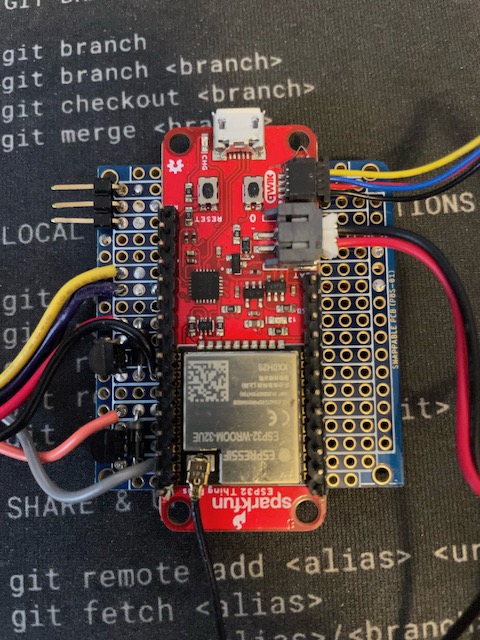
As you can see, there’s a lot going on there! So let me explain a bit. The big red board in the middle is the ESP-32 board that I am using. it is all wired up (using very thin hookup wire) to the fan and pump (the wires on the left), the servo (the connector on the left) and the soil-moisture sensor (the yellow, purple and black wires on the left).
If you look closely you’ll see a bunch of circuitry wedged in with those wires on the left, so I’ll detail that a bit.
One thing you always want to be careful of when you hook any sort of motor to a microcontroller is the possibility of a pulse of essentially reverse voltage when you turn the motor off. Most motors are designed to be powered by a 5V DC supply, so if you turn the motor off and then back on, you’ll get a pulse of reverse voltage. You can easily wreck your microcontroller board if you do not add some circuit protection. I built what’s called a Flyback Diode into these controls to prevent that.
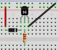
It consists of a diode, a small 220k Ohm resistor and a transistor to turn the motor on and off. The center-leg of the transistor is connected (via a 220K Ohm resistor) microcontroller pin that I use to turn the motor on and off. This allows me to switch the motor on and off using 5v instead of the minimal voltage supplied by the I/O pin.
I had to put one of those on each of the motors I connected. The servo has a built-in flyback diode so I didn’t need to build one for the servo.
The soil moisture sensor is a simple analog resistance sensor, so again, no flyback diode needed.
On the underside of this board is where all the magic happens. You can see all the tiny, thin hookup wire I used to connect everything. Soldering with this wire is not easy, so I don’t recommend it for beginners.
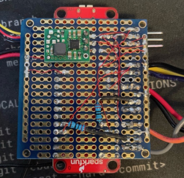
I had to use an external battery pack to supply the current for the Servo as the ESP-32 just wasn’t capable of supplying enough voltage. It could move the servo, but bot hold it in place when required.
The CO2 sensor was the easiest to connect since I used one that had a QIIC connector to handle the I2C bus. All I had to do was plug it in to the QIIC connector on the ESP-32 board and I was done. At least with the hardware part!
Now it was on to the software part.
Writing the software
I wrote this all using the Arduino as a starting point since the ESP-32 has great Arduino support. To start off, I needed to make sure I had all the right libraries in place, and all the pins for controlling everything defined:
#include <WiFiClientSecure.h>
#include <PubSubClient.h>
#include <InfluxDbClient.h>
#include <Wire.h>
#include "ESP32Servo.h"
#include "SparkFun_SCD30_Arduino_Library.h"
#include <DNSServer.h>
#include <ESPmDNS.h>
#include <WiFiUdp.h>
#include <ArduinoJson.h>

#define SERVO_PIN 19
#define FAN_CTL 15
#define PUMP_CTL 18
#define SOIL_CTL 32
#define SOIL A2
That was all I needed for those. Now it was time to make sure everything was set up and initialized correctly.
void setup() {
  Serial.begin(115200);
  pinMode(FAN_CTL, OUTPUT);
  digitalWrite(FAN_CTL, HIGH);
  Serial.println("Fan set up complete...");
  pinMode(PUMP_CTL, OUTPUT);
  digitalWrite(PUMP_CTL, LOW);
  Serial.println("Pump set up complete...");
  pinMode(SOIL, INPUT);
  pinMode(SOIL_CTL, OUTPUT);
  digitalWrite(SOIL_CTL, LOW);
  Serial.println("Soil sensor set up complete...");
  Wire.begin();
  delay(1000);
  if (airSensor.begin() == false) {
    Serial.println("Air sensor not detected. Please check wiring. Freezing...");
    while (1)
      ;
  }
  Serial.println("Air sensor detected. ");
  Serial.println("Initializing Servo...");
  ESP32PWM::allocateTimer(0);
  ESP32PWM::allocateTimer(1);
  ESP32PWM::allocateTimer(2);
  ESP32PWM::allocateTimer(3);
  door_ctl.setPeriodHertz(50); // standard 50 hz servo
  door_ctl.attach(SERVO_PIN, 1000, 2000);
  door_ctl.write(0);
  delay(1000);
  door_ctl.write(90);
  delay(1000);
  door_ctl.write(180);
  delay(1000);
  door_ctl.write(90);
  delay(1000);
  door_ctl.write(0);
  Serial.println("Servo set up complete...");
  Serial.println("Initializing WiFi...");
  WiFi.mode(WIFI_STA);
  Serial.print("Connecting to wifi");
  setup_wifi();
  while (WiFi.begin(SID, PASSWORD) != WL_CONNECTED) {
    Serial.print(".");
    delay(100);
  }
  Serial.println("");
  Serial.println("WiFi connected");
  Serial.println("Setting up MQTT ...");
  mqttClient.setServer(MQTT_SERVER, MQTT_PORT);
  mqttClient.setCallback(incoming_MQTT);
  Serial.println("MQTT set up complete...");
  timeSync(TZ_INFO, "pool.ntp.org", "time.nis.gov");
  myPoint.addTag("sensor", "GRN_CO2");
  myPoint.addTag("location", "Apex");
  myPoint.addTag("Sensor_id", SENSOR_ID);
  Serial.println("Ready");
}
Admittedly there’s a lot going on in there (and that’s not actually all of it!) so I’ll explain some. I started off setting up the pins for the fan and the pump. Oddly, one of them was on when the pin was driven high, while the other when the pin was driven low. This was the source of some consternation, believe me.
Next I set up the soil moisture sensor. I controlled it from a I/O pin because I didn’t want it powered on all the time as this would burn unnecessary power.
I then set up the CO2 sensor. I put in a fail-safe so that if the sensor wasn’t there, or couldn’t be found, the whole thing would stop. Otherwise, later when I tried to read the sensor things would go badly.
I used the ESP32PWM library to control the servo, so I had to allocate a timer for the servos, and then attach the servo to the pin. I also had to set the period of the servo to 50Hz. I dropped in some test-code so that the servo would go through it’s preset motions just for some visual feedback that it was working.
Next, I had to set up an MQTT client so that I could send messages back to the device to control it.
  mqttClient.setServer(MQTT_SERVER, MQTT_PORT);
  mqttClient.setCallback(incoming_MQTT);
  Serial.println("MQTT set up complete...");
  Serial.println("");
  timeSync(TZ_INFO, "pool.ntp.org", "time.nis.gov");
I synchronize the time in all my code because I like to use TLS for communications and it can be sensitive to time drift.
Storing the sensor data
There are a lot of choices when deciding where and how to store your sensor data. I chose to use influxdb this time because I was already storing the weather station data in influxdb and I knew that I would be able to easily query the data in a way that would allow me to synthesize the weatherstation data with the greenhouse data.
I used the Arduino InfluxDB library to connect and store the data.
influx.setWriteOptions(WriteOptions().writePrecision(WritePrecision::MS));
  influx.setWriteOptions(WriteOptions().batchSize(10).bufferSize(50));
 WiFiClientSecure *client = new WiFiClientSecure;
  if (client) {
    client->setCACert(AlphaSSLCA);
    // Check server connection
    if (influx.validateConnection()) {
      Serial.print("Connected to InfluxDB: ");
      Serial.println(influx.getServerUrl());
    } else {
      Serial.print("InfluxDB connection failed: ");
      Serial.println(influx.getLastErrorMessage());
      //  waitForInflux();
    }
  }
  myPoint.addTag("sensor", "GRN_CO2");
  myPoint.addTag("location", "Apex");
  myPoint.addTag("Sensor_id", SENSOR_ID);
  Serial.println("Ready");
That sets up my influxdb client to use a secure connection, and sets up a dataPoint object with the tags I want to use. Once all of that was done, the process was setup and ready to go!
The main loop
As it turns out, the main loop is fairly small for this. Unlike many Arduino programs I don’t use the delay() function for timing as I want the device to be interruptible by any incoming MQTT messages.
void loop() {
  if (!mqttClient.connected()) {
    reconnect();
  }
  mqttClient.loop();
  unsigned long currentMillis = millis();
  if (currentMillis - lastCO2Millis >= readingInterval) {
    lastCO2Millis = currentMillis;
    myPoint.clearFields();
    if (influx.isBufferFull()) {
      influx.flushBuffer();
    } if (airSensor.dataAvailable()) {
      co2 = airSensor.getCO2();
      float temp_c = airSensor.getTemperature();
      float hum = airSensor.getHumidity();
      int rssi = WiFi.RSSI();
      float temp_f = temp_c * 9.0 / 5.0 + 32.0;
      myPoint.addField("co2", co2);
      myPoint.addField("RSSI", rssi);
      myPoint.addField("temp_c", temp_c);
      myPoint.addField("humidity", hum);
      myPoint.addField("temp_f", temp_f);
    }
    digitalWrite(SOIL_CTL, HIGH);
    delay(10);
    int soil = analogRead(SOIL);
    digitalWrite(SOIL_CTL, LOW);
    myPoint.addField("soil", soil);
    influx.writePoint(myPoint);
  }
}
Each time through the loop I make sure that I’m connected to the MQTT broker, and make sure that I service the MQTT client in case there are any incoming messages. Since there is no delay() call, this means that the MQTT client gets serviced with great frequency.
If the time has come to take and store readings, I gather all the data and send it to influxdb. I make sure to check the buffer and send all the data if it’s full each time through.
And yes, I could do the Fahrenheit to celsius conversion in the database, but, well, I honestly have a lot of this boilerplate code left over from my days at InfluxData and I tend to just reuse stuff that works.
Controlling the greenhouse
The entire point of this project was to be able to control it with Camunda so it’s time to dive in to that!
I’ll give you a minute to catch your breath before I dive in to explaining it.
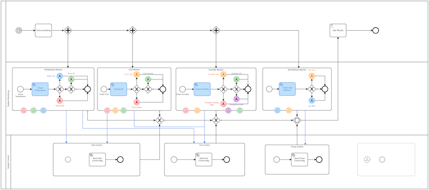
First the easy part. I start the whole process with a Timer Event that fires every 2 minutes. I really don’t need to run it that frequently, in a real world scenario, but I wanted to make sure that I could see things run and change, so I set the timer very low.
That timer event kicks off a series of sub-processes via some parallel gateways. I want all of these sub-processes to run simultaneously, so this is the way to make that happen.
I’ll walk through one of the sub-processes in detail but just know that each one of them is essentially the same.
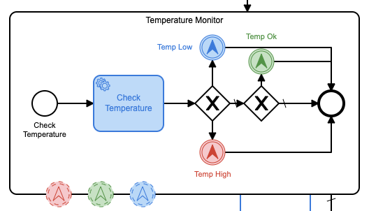
This sub-process calls an external service (which I’ll get to in a minute) to get the current CO2 level. It then compares that threshold to the various thresholds that I’ve set, and sends a message to the MQTT broker to trigger an appropriate action based on the level. I’ve color-coded them so it’s easy to see what happens when.
The nice part about using Camunda to control the process is that, should the needs of the plants change, I don’t have to go re-code any of the sensors. I can just come in to this model, set new thresholds, and redeploy the process. This is the really important part about using Camunda to control everything. I’m actually planning to go back and integrate Camunda into a bunch of older sensing projects I have that use hard-coded thresholds and settings so that I can set everything – and change it – from a process management application rather than having to recompile everything each time.
In the world of IoT, deploying new firmware can easily be a very expensive and time-consuming process, so doing it this way will be a huge savings.
The external service
As I said, the handling of the database query is done via an external service. I’ve become quite enamored with Go, so I wrote the external service using it.
This service will use 3 important libraries:
- The Camunda Client Library
- The Paho MQTT Library
- The InfluxDB v2 Library
This allows me to listen for work from the Camunda process, query the database, and then send messages to the MQTT broker when required.
the first thing that’s required is to set up the Camunda client:
client := camundaclientgo.NewClient(camundaclientgo.ClientOptions{
		UserAgent:   "",
		EndpointUrl: "http://localhost:8080/engine-rest",
		Timeout: time.Second * 10,
		ApiUser: "demo",
		ApiPassword: "demo",
	},
	)
	asyncResponseTimeout := 5000
	// get a process instance to work with
That is the client that the rest of the process will use. Next, I’ll need a Camunda Processor to so that I can listen for tasks.
	proc := processor.NewProcessor(client, &processor.ProcessorOptions{
		WorkerId:                  "GreenHouseHandler",
		LockDuration:              time.Second * 20,
		MaxTasks:                  10,
		MaxParallelTaskPerHandler: 100,
		LongPollingTimeout:        25 * time.Second,
		AsyncResponseTimeout:      &asyncResponseTimeout,
	}, logger)
	log.Debug("Processor started ... "
Now that I have a processor, I can start adding handlers to listen for the specific topics that I want to handle.
	// add a handler for checking the existing Queue
	proc.AddHandler(
		&[]camundaclientgo.QueryFetchAndLockTopic{
			{TopicName: "checkCO2"},
		},
		func(ctx *processor.Context) error {
			return checkCO2(ctx.Task.Variables, ctx)
		},
	)
This particular handler will listen for messages on the checkCO2 topic. It will then call the checkCO2 function to do the work.
I’ve defined the checkCO2 topic in the properties panel for the external task in Camunda Modeler.
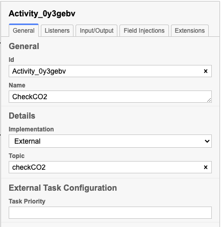
So let’s look at the chekcCO2() function.
func checkCO2(variables map[string]camundaclientgo.Variable, ctx *processor.Context) error {
	// Create a new client using an InfluxDB server base URL and an authentication token
	client := influxdb2.NewClient("https://influxserver.com:8086", "long_influxdb_token_string")
	// Get query client
	queryAPI := client.QueryAPI("influxdata")
	// get QueryTableResult
	result, err := queryAPI.Query(context.Background(), `from(bucket: "telegraf")
  |> range(start: -1m)
  |> filter(fn: (r) => r["_measurement"] == "greenhouse")
  |> filter(fn: (r) => r["_field"] == "co2" )` )
	var averageCO2 float64 = 0.00
	var numResults int = 0
	if err == nil {
		// Iterate over query response
		for result.Next() {
			// Access data
			foo := fmt.Sprintf("%v", result.Record().Value())
			foo64, err := strconv.ParseFloat(foo, 64)
			if err != nil {
				fmt.Println("bad value!")
        return err
			}
			averageCO2 = averageCO2 + foo64
			numResults++
		}
		// check for an error
		if result.Err() != nil {
			fmt.Printf("query parsing error: %s\n", result.Err().Error())
		}
		averageCO2 = (averageCO2 / float64(numResults))
		if math.IsNaN(averageCO2) {
			fmt.Println("Bad value! No donut!")
			averageCO2 = 0.00
		}
		varb := ctx.Task.Variables
		varb["co2"] = camundaclientgo.Variable{
      Value: averageCO2,
      Type: "double"
    }
		err := ctx.Complete(processor.QueryComplete{Variables: &varb})
		if err != nil {
			log.Error("queuStatus: ", err)
			return err
		}
	} else {
		log.Error("queuStatus: ", err)
		return err
	}
	Crop.CO2 = averageCO2
	// Ensures background processes finishes
	client.Close()
	return nil
}
So that’s a lot of Go code! If you’re not familiar with Go, you most likely have no idea what any of that does, so let’s walk through it. First, I’m creating a new client using the InfluxDB client library. I’ll need this in order to query the database. Next come the actual query, which is written in flux, the query language that InfluxData invented to query their database. I’m using the from function to specify the bucket that I want to query. Then I’m using the range function to specify the time range. Then I’m using the filter function to filter out the data that I want to query. The range is just the last minute, and if I wanted to I could also have Flux query the last n minutes and return the average itself, but I’m doing it here just for fun.
Once I’ve calculated the average, I need to return that value to the Camunda process, so I create a process variable and set it to the calculated average.
I then return that variable to the Camunda engine and tell it that I have completed the task. That’s all.
I wrote one of these process handlers for each of the database queries I wanted to make so that each database query could be a handled as a separate task.
Some of you may have noticed that I didn’t use any of the data from the weather station to inform these decisions. You are entirely correct. Here’s why: the small greenhouse is sitting inside, on a desk. So the outside conditions have absolutely no bearing on what opening vents, etc. would affect the greenhouse. So I left them out.
Taking action from Camunda
As we’ve seen above, the Camunda engine will call each of these sub-processes to query the database simultaneously (or close to it). Once the query os complete, the proper value is returned, and the Camunda engine will continue to process the next task.
These query tasks then either simply end (if there is nothing to be done) or they throw an Intermediate Escalation Event depending on which threshold is exceeded. To follow this through, let’s take a look at what happens when we query the soil moisture sensor.
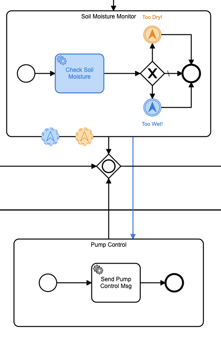
This sub-process has 2 escalation states: too wet and too dry. That’s it. The Camunda engine will throw that escalation event depending on the result. We then have another sub-process that is sitting around waiting for either one of those escalation events to happen. This sub-process controls the pump that will water the plants. If the soil moisture is too dry, the pump will be turned on. If the soil moisture is too wet, the pump will be turned off.
Side note: The small water pump I used was overly-capable of pumping water. If it were left on even for a minute the entire greenhouse flooded, so I had to adjust this later to turn the pump on for a specific period of time, depending on the soil moisture level. The maximum I ever left it on was for no more than 7 seconds. I settled for a value of 5 seconds.
Let’s take a look at how that sub-process works. The Soil Moisture Monitor sub-process will notify the Pump Control sub-process if we need to turn the pump on or off. If the soil is too dry, the escalation event will contain the following JSON:
{
  "sensor": "soil-dry",
  "commands" : {
    "fan": "none",
    "vent": "none",
    "pump": "on"
  }
}
In fact, all of the escalation events contain a similar JSON object containing the actions to take. In fact, if we take a look at the CO2-Critical escalation event we see:
{
  "sensor": "co2-critical",
  "commands" : {
    "fan": "on",
    "vent": "open",
    "pump": "none"
  }
}
Because when the CO2 is high, we have to do all we can to get it lowered, and fast! So we turn on the fan and open the vent all the way.
The “action” sub-processes then take these JSON payloads in the escalation events and put them in the queue of another external process with the name control.
Let’s go through that external implementation as well. I’ll break it up so it’s not a wall of code so I can go through it bit by bit.
func control(variables map[string]camundaclientgo.Variable,ctx *processor.Context) error {
	var tlsConf *tls.Config = nil
	tlsConf = &tls.Config{
		InsecureSkipVerify: true,
	}
	var opts = mqtt.ClientOptions{
		ClientID: "greenhouse",
		Username: "",
		Password: "",
		TLSConfig:            tlsConf,
		KeepAlive:            0,
		PingTimeout:          0,
		ConnectTimeout:       time.Second * 10,
		MaxReconnectInterval: 0,
		AutoReconnect:        false,
		ConnectRetryInterval: 0,
		ConnectRetry:         false,
		Store:                nil,
	}
  opts.AddBroker("tcp://my-broker.com:8883")
	opts.SetClientID("greenhouse")
	opts.SetMaxReconnectInterval(time.Second * 10)
	var client = mqtt.NewClient(&opts)
	token := client.Connect()
	for !token.WaitTimeout(3 * time.Second) {
	}
	if err := token.Error(); err != nil {
		return err
	}
This is all really just the setup code for using the Paho MQTT client. My MQTT broker uses TLS, so I have to set that up as well.
  incoming := ControlMsg{}
	varb := fmt.Sprintf("%v", ctx.Task.Variables["action"].Value)
	fmt.Printf("Raw: %v\n", varb)
	err := json.Unmarshal([]byte(varb), &incoming)
	if err != nil {
		return err
	}
	fmt.Println("Incoming Sensor: ", incoming.Sensor)
	fmt.Printf("Incoming Commands: %v\n", incoming.Commands)
As with the previous external task handler, I get the variables from the process engine that I need. Since I sent those variables as a JSON object, I can unmarshal the data into my ControlMsg struct.
Wait, I didn’t share that with you!
type ControlMsg struct {
	Sensor   string `json:"sensor"`
	Commands struct {
		Fan  string `json:"fan"`
		Vent string `json:"vent"`
		Pump string `json:"pump"`
	} `json:"commands"`
}
That should look suspiciously like the JSON object that was in the escalation event.
Now that I have those messages, I can turn around and publish them to the MQTT broker.
		t := client.Publish("greenhouse", 0, false, varb)
		go func() {
    	_ = t.Wait()
    	if t.Error() != nil {
        log.Error(t.Error())
    	}
		}()
Once the mqtt message is sent, I can then complete the process just as I’ve done before:
	varbs := ctx.Task.Variables
	varbs[incoming.Sensor] = camundaclientgo.Variable{
    Value: incoming.Sensor + " completed",
    Type: "string"
  }
	err = ctx.Complete(processor.QueryComplete{Variables: &varbs})
	if err != nil {
		log.Error("queuStatus: ", err)
		return err
	}
	client.Disconnect(250)
	return nil
}
And now the message has been sent, and the ESP-32 controller in the greenhouse will receive that message and act on it appropriately.
Since I left that part of the Arduino code out earlier, let’s take a look at that now:
void incoming_MQTT(char *topic, byte *payload, unsigned int length) {
  StaticJsonDocument<200> doc;
  DeserializationError error = deserializeJson(doc, payload);
  if (error) {
    Serial.println(error.f_str());
    return;
  }
  const char *fan = doc["commands"]["fan"];
  const char *vent = doc["commands"]["vent"];
  const char *pump = doc["commands"]["pump"];
  if (fan) {
    if (strcmp(fan, "on") == 0) {
      digitalWrite(FAN_CTL, LOW);
    } else if (strcmp(fan, "off") == 0) {
      digitalWrite(FAN_CTL, HIGH);
    }
  }
  if(pump) {
    if (strcmp(pump, "on") == 0) {
      digitalWrite(PUMP_CTL, HIGH);
    } else if (strcmp(pump, "off") == 0) {
      digitalWrite(PUMP_CTL, LOW);
    }
  }
  if(vent) {
    if (strcmp(vent, "open") == 0){
      door_ctl.write(180);
      pos = 180;
    } else if (strcmp(vent, "close") == 0) {
      door_ctl.write(0);
      pos = 0;
    } else if (strcmp(vent, "half") == 0) {
      if(pos == 0 || pos == 180) {
        door_ctl.write(90);
        pos = 90;
      } else if (pos == 90) {
        // already half
      }
    }
  }
}
The external task handler sent the JSON object it received from the Camunda topic on to the MQTT broker, which then forwarded it on to the ESP-32, so this function deserializes the object into a JSON document. Once that’s done. I can access the various fields of the document to decide what needs to happen.
Maybe you’re starting to see now why I designed the escalation events the way I did!
I can act on all of the various control messages in the JSON, and then return. This code will actually flood my greenhouse because it simply turns the pump on or off, rather than turning it on for a specific time period.
if(pump) {
    if (strcmp(pump, "on") == 0) {
      digitalWrite(PUMP_CTL, HIGH);
      delay(5000);
      digitalWrite(PUMP_CTL, LOW);
    }
  }
Is a much better version of this as it only turns the pump on for 5 seconds at a time. Your values might differ, depending on the pump you’re using.
In fact, had I realized the strength of the pump ahead of time, I would have made the length of time to turn the pump on part of the escalation event from the Camunda process so that I could compensate for different pumps at a higher level, rather than having to recompile and redeploy firmware depending on the pump.
Conclusions
I hope that you can see the value of using a business process management platform to orchestrate an IoT process like this. I was skeptical at first myself until I started to see the overall benefits.
I could have made some things updateable over Over The Air updates, but this means recompiling and redeploying firmware.
I could have made the various levels of CO2, temperature, etc. hard-coded values, but then I’d have to recompile and re-deploy firmware to change to a crop that has different needs.
I could have made the various monitored levels part of the external process and forgone the entire BPMN orchestration, but then in order to change anything I’d have to have an engineer go in and make changes to the code.
By using a high-level BPMN process I can see the overall process at a glance. I can see what is monitored and what is acted on. I can even make changes to how the entire greenhouse runs without ever writing any code at all. Anyone could go in to the model, change the values for a new crop, redeploy the model with a single click, and change everything about how that crop is managed.
I have every intention of using Camunda to orchestrate and control most, if not all, of my IoT projects from here on out just so that I can more easily change how they run and how they function without all the re-compiling and deployment of firmware that I’ve been doing up to now.